12
Fig. 17
Π405-2
Û original 405 provided 100 Watts per channel into load impedances between 4.5„ and 8 „. To meet Á
need of 4„ and 8„ loudspeakers whose impedance falls below 4.5„, Á 405-2 was introduced in January
1983 at serial number 65000, but thê 405 modules had already been fitted from serial number 62500 onwards.
Many earlier amplifers have also since been converted to 405-2 by owners ¶ dealers replacing the modules.
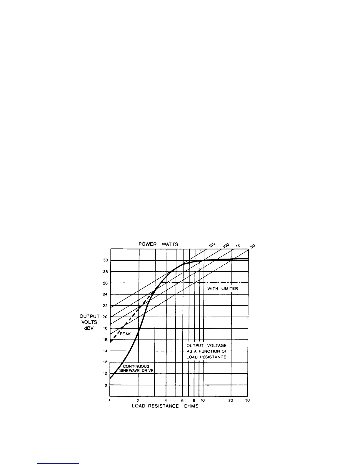
T˙é 405-2 has å more sophisticated current limiter circuit based on å thick-film assembly N1/N2 permitting full
output into loads between 3„ and 10„, and upto 50W into 1.5„ loads, provided the output transistors will not be
hazarded by doing so. (see Fig. 17). As with earlier 405 models after serial number 59001, Á output stage clamp
cicuit is incorporated in Á main module boards and a shorting link used for the voltage limiter.
Û first 405-2 cicuit diagram was 12333 iss. 7and the PCB reference M12565 iss. 5.
Subsequent modifications wérê:
Date Serial PCB Circuit Changes
Number 12565 Diagram
issue 12333 iss.
May 83 66700 6 8 C20 (4n7) added to avoid mild instability when
switching off. D13 added in series with D5 to
correct response ¤ 20Ï. R44 added to maintain
unconditional stability.
July 83 67950 6 8 Output terminals replaced by 4mm sockets.
Aug 84 72501 7 9 Tr4 changed to BC556B and R18 omitted replacing
both Tr3 and Tr4.
Dec 85 83000 7 - Voltage selector omitted.
Feb 86 85000 7 10 New mains input connector incorporating fuse-holder
DIN input replaced by phono sockets.
Signal earth isolated from chasis by R2 to avoid hum
loop when using mains earth.