TEST EQUIPMENT
Sound Technology Distortion Analyser 1700A (ST1700A)
Dual Beam Oscilloscope
4„ and 8„ load of 100W dissipation
1„ load of 25W dissipation
2.5 kHz Square Wave Generator
Input Sensitivity Indicator (0 to 1V RMS)
AVOmeter (or similar multitester)
0 to 12V d.c. power supply
Variac a.c. power supply
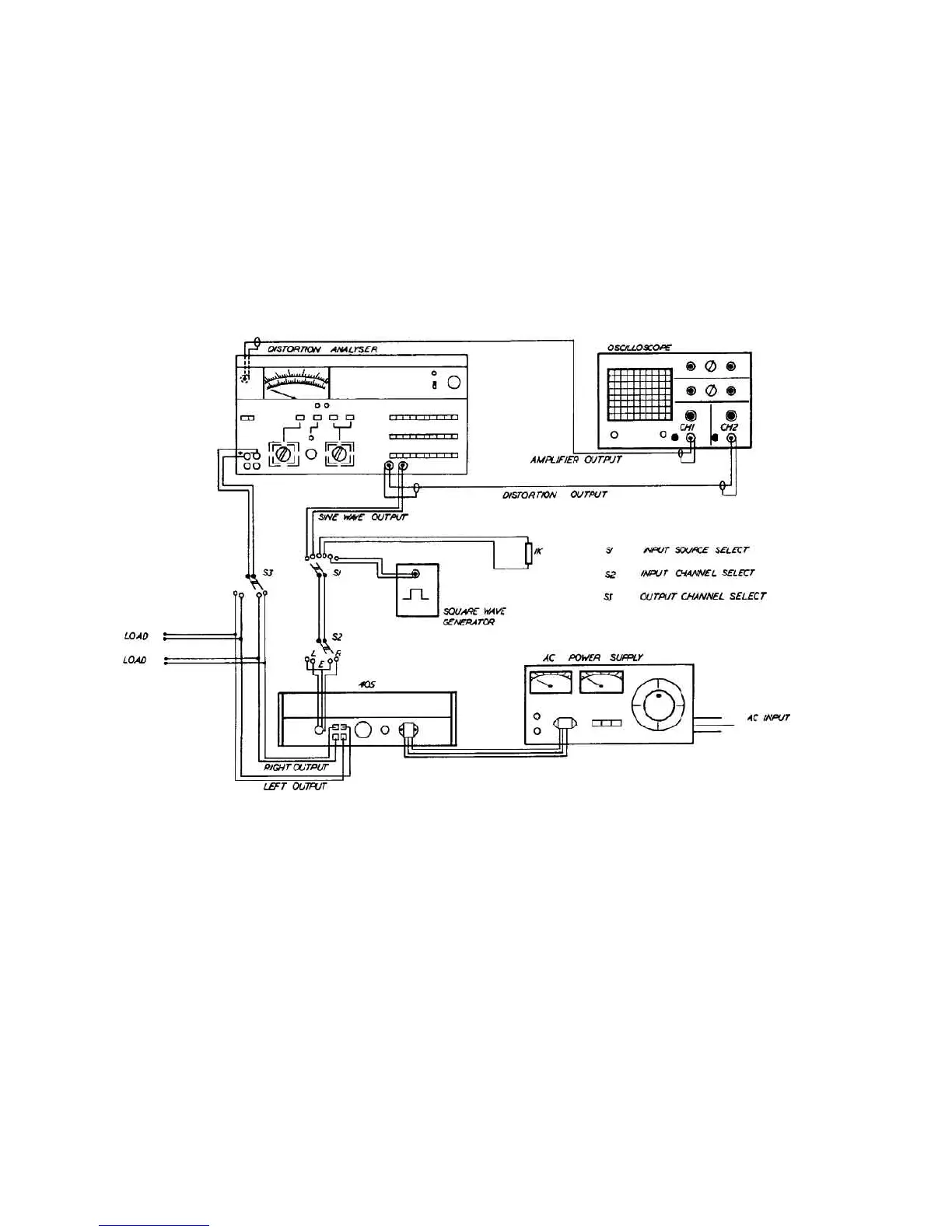
Fig. 2 illustrates a simple switching circuit which may assist if much testing is anticipated.
SUGGESTED SWITCHING ARRANGEMENT FOR TESTING QUAD 405
Fig. 2
Before testing, Á cover of Á 405 should be removed.
DISCONNECTING CLAMP CIRCUITS
When servicing å 405 fitted with a clamp circuit, it may be necessary to bypass this circuit.
For 405s fitted with amplifier boards M12368, this may be done by removing t˙´ push-on connectors carrying Á
brown wires from Á amplifier boards, and connecting Á loads between Á black output terminals and Á
output terminals on Á amplifier boards.
For 405s fitted with amplifier boards type M12565, it will be necessary to remove thë side panels to gain access
to Á printed copper side of Á amplifier boards. Á three screws securing each side panel should be removed,
Á panel may thën bê slid outwards from Á amplifier. If Á solder is removed from Á link pad shown in Fig.18
(A), Á clamp circuit will become disconnected.
Care should be taken to ensure that when testing is completed, Á link pad is rë-soldered.
4