Fig. 15
1. Disconnect the wiring to thë right channel circuit board and fold it back onto the transformer. Loosen the
clamp holding the electrolytic capacitor next to the output terminals, and lift Á capacitor out of the way.
2, Disconnect Á leads to the output sockets, place the clamp board over the output connectors and re-solder.
It is advisable to tin the output connector tags before positioning Á clamp board. This makes soldering easier.
Replace the capacitor and reconnect the tags to thé right channel amplifier board.
CLAMP CIRCUIT ALTERNATIVES
T1 - 2N4992 or BS08A-03
T2 - Sc141B or TIC226B or RCA T2800
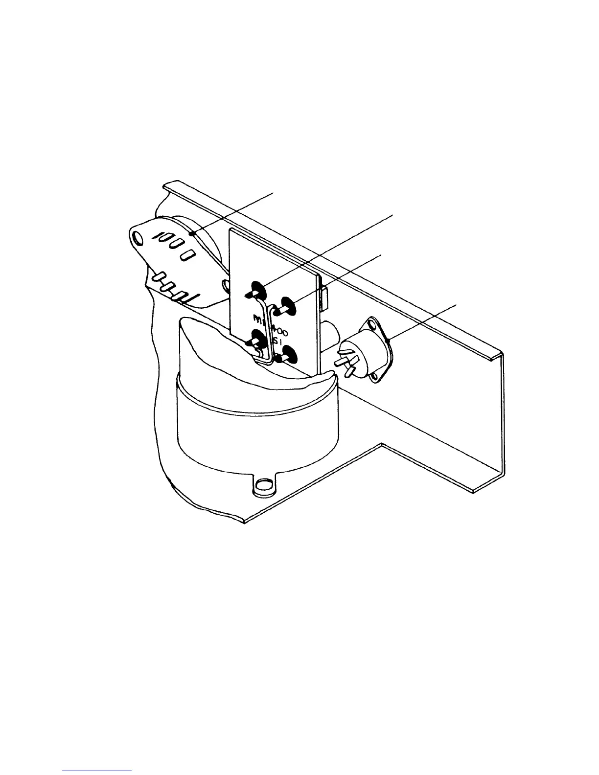
Fig. 15
VOLTAGE SELECTOR
SOLDER BOARD & WIRES
TO OUTPUT SOCKETS
OUTPUT SOCKETS
INPUT SOCKET
9
CLAMP CIRCUIT
Introduced co-incident with amplifier PCB M12368 iss. 9 ¤ serial number 9001. All 405s with serial numbers 9000
¶ under being returned for service, should be fitted with å clamp board as shown below.
At serial number 59001 Á clamp circuit was fitted as an integral part of the amplifier board M12565 iss. 3.
Û function of this circuit is to monitor t˙ê d.c. component of the output. In the event of å component failure
which causes excessive d.c. voltage, thé circuit will short circuit the amplifer output ¶ thus protect the speakers.
REPLACING THE CLAMP BOARD
If it is necessary to replace å clamp board the following instructions should be followed: