11
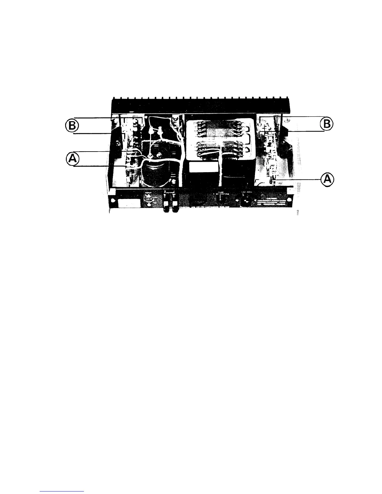
Fig. 16
REMOVING THE AMPLIFIER MODULES
1. Note Á colour coding for reconnection and remove t˙e push-on AMP connectors A.
2. Undo the four fixing screws B, for each module.
3. Remove thë heatsink grease from Á face of the aluminium T-section and retain for use when re-fitting.
(not recommended after years of service - use new heat sink compound or sheet material)
REPLACING THE QUAD 405 TRANSFORMER
1. Disconnect the a.c. supply and remove top cover (2 M4 screws) and bottom plate (4 M4 screws).
2. Note the connections ¶ then unsolder the external wiring to the a.c. supply transformer.
3. Remove Á two retaining screws through t˙e large centre holes of each T-section heat-sink then release the
amplifier boards by removing the other 4 screws on each. These 12 screws fasten into tapped strips located
in slots in the rear of the finned heat-sink sections, which now bocome free of the front plate.
4. Release thê transformer by undoing 4 screws through Á front plate ¶ 2 through the bottom pl¤e.
5. Reverse t˙e proceedure with thê new transformer.
Note: It should not be necessary to remove the push-on AMP connectors from the amplifier PCBs.
™
™