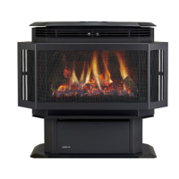
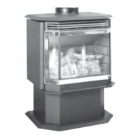
EasyManua.ls Logo

Quadra-Fire HUDSON BAY HUDBAY-FS User Manual

Quadra-Fire HUDSON BAY HUDBAY-FS
50 pages
To Next Page IconTo Next Page
Page #1 background imageLoading...
Page #1 background image
R
HUDSON BAY
DIRECT VENT GAS APPLIANCE
Owners Manual
Installation and Operation
Model:
HUDBAY-FS
• Important operating and
maintenance instructions
included.
Leave this manual with
party responsible for use
andoperation.
• Read, understand and
followtheseinstructions
forsafeinstallationand
operation.
This appliance may be installed as an OEM installation in
manufacturedhome(USAonly)ormobilehomeandmustbe
installedinaccordancewiththemanufacturer'sinstructionsand
themanufacturedhomeconstructionandsafetystandard, Title
24 CFR, Part 3280 or Standard for Installation in Mobile Homes,
CAN/CSA Z240MH.
Thisapplianceisonlyforusewiththetype(s)ofgasindicated
ontheratingplate.
Installation and service of this appliance should be
performed by qualied personnel. Hearth & Home
TechnologiessuggestsNFIcertiedorfactory-trained
professionals, or technicians supervised by an NFI
certiedprofessional.
IntheCommonwealthofMassachusetts:
• installationmustbeperformedbyalicensedplumberorgas
tter.
See Table of Contents for additional Commonwealth of
Massachusettsrequirements.
HOT SURFACES!
Glassandothersurfacesarehotduring
operationANDcooldown.
Hot glass will cause burns.
• Donottouchglassuntilitiscooled
• NEVERallowchildrentotouchglass
• Keepchildrenaway
O-T L
Tested and
Listed by
Portland
Oregon USA
OMNI-Test Laboratories, Inc.
C
US
CAUTION
DO NOT
DISCARD
WARNING: If the information in these
instructions is not followed exactly, a re
or explosion may result causing property
damage, personal injury, or death.
• Donotstoreorusegasolineorotherammable
vaporsandliquidsinthevicinityofthisorany
otherappliance.
What to do if you smell gas
- D o n o t t r y t o l i g h t a n y a p p l i a n c e . 
Do not touch any electrical switch. Do not
useanyphoneinyourbuilding.
- Immediately call your gas supplier from a
neighbor’sphone.Followthegassupplier’s
instructions.
- Ifyoucannotreachyourgassupplier,callthe
redepartment.
• Installationandservicemustbeperformedby
aqualiedinstaller,serviceagency,orthegas
supplier.
WARNING
!
CAREFULLY SUPERVISE children in same room as
replace.
• Alertchildrenandadultstohazardsofhightemperatures.
High temperatures may ignite clothing or other ammable
materials.
• Keep clothing, furniture, draperies and other flammable
materialsaway.
Quadra-Fire•HudsonBay•7003-121_R19•7/14
DO NOT DISCARD THIS MANUAL

Table of Contents

Questions and Answers:

Quadra-Fire HUDSON BAY HUDBAY-FS Specifications

General IconGeneral
Fuel TypeWood
Firebox Size2.0 cu ft
Maximum Log Size18 inches
Flue Size6 inches
EPA CertifiedYes
Blower IncludedOptional
Heating CapacityUp to 2, 000 sq ft
FinishMatte Black

Summary

Safety Warnings and Precautions

Fire and Explosion Hazard Warnings

Follow instructions to prevent fire or explosion, which may cause property damage or injury.

Handling Gas Leaks

In case of gas smell, do not light appliance, use phone, or switches. Call gas supplier or fire department.

Hot Surface Burn Hazard

Appliance surfaces are hot during operation and cool down; avoid touching to prevent burns.

Child Supervision and Clearances

Supervise children closely and keep them away from hot surfaces and flammable materials.

Massachusetts Installation Requirements

Carbon Monoxide Detector Mandate

Requires hard-wired and battery-operated CO detectors on all levels for horizontally vented appliances.

Signage for Horizontal Vent Terminations

Mandates a sign stating 'GAS VENT DIRECTLY BELOW. KEEP CLEAR OF ALL OBSTRUCTIONS.'

Appliance Location and Clearances

Clearances to Combustibles Diagram

Diagram and table provide minimum clearances (A-H) to combustible materials.

Vent Termination Locations

Vent Termination Minimum Clearances

Maintain specified clearances to combustibles; do not pack air space with insulation or materials.

Horizontal Vent Termination Clearances

Diagrams illustrate minimum horizontal clearances for vent termination caps.

Vertical Vent Termination Height

Table shows minimum vent heights from roof to discharge opening based on roof pitch.

Vent Terminal Clearances and Restrictions

Vent Terminal Clearance Measurements

Diagrams and measurements define clearances to grade, windows, doors, soffits, and corners.

Prohibited Vent Terminal Locations

Specifies areas where vent termination is prohibited, like near mechanical inlets or certain sidewalks.

US and Canada Vent Termination Warnings

Warns against termination in screened porches (US) and notes Canadian porch requirements.

Vent System Information

Approved Venting Components

Lists approved venting component manufacturers; warns against field-fabricated components.

Vent Graph and Installation Guidelines

Using the Vent Graph for Horizontal Runs

Step-by-step guide to determine maximum horizontal vent run based on vertical distance.

Venting Guidelines and Limitations

Specifies max horizontal run, vertical rise, wall thickness, elbow limits, and support requirements.

Horizontal Vent Termination Installation

Vent Pipe Connection and Locking Mechanism

Connect vent pipe sections using twist-lock adapter and female locking lugs.

Cutting and Framing Wall Opening

Details marking and cutting a 10x10 inch hole for wall thimble or a 7-inch hole for masonry.

Horizontal Termination Details

Horizontal Vent Run Pitch and Location

Requires 1/4 inch rise per foot of horizontal run; termination must not be blocked or obstructed.

Attaching Termination Cap to Exterior Wall

Instructions for positioning, sealing, and screwing the termination cap to the exterior wall.

Vent Assembly and Termination Cap Installation

Connecting Vent Pipe to Termination Cap

Connect vent pipe to termination cap using sheet metal strips and screws; seal with silicone.

Vertical Vent Termination Installation

Maximum Vertical Rise and Offset Limits

Maximum vertical rise is 40 ft (12m); offsets must comply with vent graph parameters.

Vertical Termination Installation Steps

Vertical Termination Steps (Continued)

Enclosure Requirements for Vertical Vents

Occupied areas above first floor must be enclosed; maintain clearance and do not fill air space with insulation.

Masonry Chimney Installation Steps

Flex Liner Sagging Hazard Warning

Do not let flex liner sag; this can trap hot gas and create a fire hazard.

Gas Information and Fuel Conversions

Fuel Compatibility and Conversion Procedures

Ensure appliance compatibility with gas type; conversions must be done by qualified technician.

Valve Regulator Replacement Procedure

Replacing Pressure Regulator Assembly

Remove regulator tower and diaphragm; install new HI/LO pressure regulator assembly securely.

Gas Pressure Requirements and Verification

Gas Pressure Safety Warnings

Warnings about high pressure, disconnecting supply, and closing shutoff valves during testing.

Verifying Inlet Gas Pressures

Verify inlet pressures; high pressure can cause overfire, low pressure can cause explosion.

Gas Connection Procedures and Safety

Gas Leak Testing and Control Valve

Leak test all joints and control valve; support control to prevent bending gas line.

Purging Gas Lines and Ventilation

Purge air from lines; ensure ventilation and no ignition sources. Air needs purging after OFF.

Checking for Gas Leaks

Check fittings for leaks using non-corrosive solution; do not use open flame.

Log Set Positioning Instructions

Log and Mineral Wool Placement

Blower Installation Procedure

Damper and Shutter Adjustment

Damper Adjustment for Flame Appearance

Adjust vertical damper based on vent graph to improve flame appearance; use 'flue restrictor' in MA.

Shutter Adjustment for Flame Color

Adjust shutter to control flame height and color; closing creates taller orange flames.

Operating Instructions and Safety

Before Lighting Appliance Checklist

Read manual, remove shipping materials, check logs, wiring, baffle, gas leaks, and seals.

Glass Door Safety Requirements

Glass door must be in place and sealed during operation to prevent fumes and fire risk.

Hot Surface and Burn Hazard Warnings

Surfaces are hot during operation; keep children away and supervise them closely.

Appliance Operation After Water Exposure

Do not use if part has been under water; call technician immediately to inspect and replace controls.

Lighting the Appliance Pilot and Main Burner

Safety Warnings Before Lighting

Follow instructions exactly to prevent fire or explosion. Smell for gas before lighting.

Pilot Flame Ignition Steps

Steps to light the pilot using the control knob and piezo ignitor; hold knob for 30 seconds.

Verifying Pilot Light and Main Burner

After pilot is lit, hold knob, release. If pilot stays lit, proceed to turn main burner ON.

Post-Lighting Procedures and Break-in

Initial Break-in Procedure

Run appliance for 3-4 hrs on high, cool, clean glass, then run for 12 additional hrs to cure.

High Temperature and Combustible Warnings

Keep combustibles away; do not obstruct air flow; keep furniture and draperies away.

Troubleshooting Common Appliance Issues

Pilot Ignitor Not Lighting

Check ignitor, pilot electrode gap, gas pressure, or LP fuel level.

Pilot Not Staying Lit

Check thermocouple connection/impingement or valve defect.

Burner Not Igniting with Pilot Lit

Check ON/OFF switch, wires, thermopile millivoltage, or valve.

Troubleshooting Continued

Pilot Flame Issues and Valve Defects

Addresses pilot flame height, defective valve, plugged burner orifice, and switch/wire issues.

Pilot Outage and Burner Extinguishing

Check LP tank, vent leaks, horizontal vent pitch, thermopile/thermocouple, vent cap.

Glass Sooting and Blue Lifting Flames

Adjust logs for impingement, check shutter, clean burner opening, ensure sufficient oxygen.

Appliance Maintenance and Servicing

Servicing Safety Precautions

Turn off gas and electricity, ensure appliance is cooled before servicing.

Annual Inspection Recommendations

Check glass, seals, air passages, termination cap, burner, and gas connections annually.

Detailed Maintenance Tasks Checklist

Burner Ignition and Operation Checks

Verify burner alignment, clean ports, check millivolt output, pilot strength, and pressures.

Service Parts Identification

Pedestal and Valve Component Identification

Additional Service Parts

Limited Lifetime Warranty Coverage

Warranty Coverage Terms and Conditions

Warrants against defects in materials/workmanship; HHT may repair, replace, or refund.

Warranty Conditions, Exclusions, and Limitations

Warranty Conditions: Authorization and Location

Warranty valid only for appliances purchased through authorized dealers and at the site of original installation.

Warranty Exclusions: Normal Use and Damage

Excludes damage from fingerprints, misuse, accidents, improper installation, or unauthorized modifications.

Warranty Void Conditions

Warranty void if appliance is over-fired, operated in contaminated atmospheres, or damaged by water.

Related product manuals