Do you have a question about the Qualitrol 509ITM Series and is the answer not in the manual?
Details on Qualitrol's history, products, and manufacturing capabilities.
Information on safety symbols, warnings, and operational disclaimers.
Introduction to the 509ITM and its available input types.
Guidance on how to use the hardware instructions manual for the 509ITM.
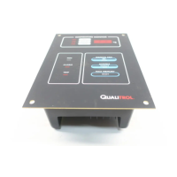
Description of the display and keypad functions on the 509ITM front panel.
List and brief description of the various input modules available for the 509ITM.
Step-by-step guide for unpacking and installing the 509ITM unit.
Details on enclosure and panel mounting options for the 509ITM.
Information on connecting the universal power supply to the 509ITM.
Details on connecting and configuring the optional heater for the 509ITM.
Description of output contacts, relay ratings, and wiring for the 509ITM.
Details on the four milliamp (mA) current outputs for remote indication or SCADA.
Information on RS-485, Fiber Optic, and Ethernet communication capabilities.
How to navigate and operate the 509ITM in automatic and menu modes.
Instructions for accessing and changing monitor settings in program mode.
Details on monitoring the transformer cooling system using the 509ITM-200.
Details on monitoring the load tap changer system using the 509ITM-300.
Information on performing system tests and key functional specifications.
Overview of the 509ITM software, connection, and installation procedures.
Steps for establishing communications and troubleshooting link failures.
Description of available software tools: Monitor, Simulator, Calibrator, etc.
Navigating and using the Customer-Setup and Factory-Setup windows.
Configuring passwords, features, time, date, display, and heater settings.
Setting up communication parameters for USB, RS-485, and Ethernet ports.
Configuring individual input modules, including type, function, and signal name.
Defining custom scaling values for input signals to adjust measurement ranges.
Configuring parameters for CT current and calculated winding temperature.
Detailed setup for each relay, including failsafe, test lockout, and latching.
Configuring seasonal setpoints and ambient temperature forecasts for relays.
Setting up cooling equipment exerciser and matrix control logic for relays.
Setting up the four software selectable current loop output channels.
Configuring bank switching to evenly spread cooling equipment wear.
Configuring TransLife settings for individual winding temperatures.
Calculating transformer consumed life based on IEEE standards.
Using critical forecast and temperature profiler for transformer life analysis.
Configuring the data logger to store up to 20 signals.
Logging user-selectable events, system snapshots, and event triggers.
Configuring parameters for each cooling bank, including current and time settings.
Using the learning mode to obtain parameters for cooling system initialization.
Setting up the LTC monitor, including tap position and current measurement.
Configuring high and low priority alarms for the LTC monitor.
Setting up difference calculations and viewing LTC tap values.
Using fiber optic probes for direct winding temperature measurement.
Details on fiber optic probes, plates, junction boxes, and modules.
Saving and restoring 509ITM configurations and calibration values.
Description of the expansion module for doubling input capabilities.
Diagram and details for panel mounting the 509ITM unit.
Wiring specifications for input power and communications to expansion modules.
Overview of DGA monitors, sensor installation, and wiring diagrams.
Procedure for verifying DGA sensor correlation with laboratory results.
Guidelines for interpreting DGA readings and setting up relay actuation.
Steps for recalibrating current loop outputs to alternate values.
Procedure for calibrating a Level Gauge (Potentiometer) to the 509ITM.
Procedure for calibrating a Tap Position Resistor Bridge to the 509ITM.
| Category | Transformer Monitor |
|---|---|
| Monitored Parameters | Moisture |
| Communication Protocols | Modbus, DNP3 |
| Power Supply | 24 VDC |
| Operating Temperature | -40°C |