Do you have a question about the Quanmax KEEX-4030 and is the answer not in the manual?
Guidelines for safe handling and operation of the computer.
Steps to take before opening the computer for maintenance.
Procedures to prevent damage from static electricity.
Instructions on how to use the user manual effectively.
Steps for unpacking the product and checking contents.
FCC compliance statement for Class A digital devices.
Details the limited warranty terms and conditions for the product.
Steps for returning products under the warranty policy.
Disclaimer of liability for product defects or damages.
Guidance on maintaining the computer's operational environment.
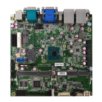
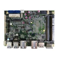
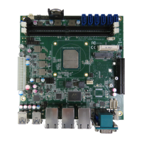
Introduction to the KEEX-4030 SBC and its key features.
Detailed technical specifications of the KEEX-4030 motherboard.
Visual representation of the system's architecture and component connections.
Physical dimensions and mounting hole layout of the board.
Introduces the chapter on jumpers, headers, and connectors.
Explanation of jumper configuration for system operation.
Diagrams and locations of jumpers and connectors.
Detailed descriptions and functions of various jumpers.
Pin assignments for rear panel connectors.
Pinout for the HDMI1 connector.
Pinout for the COM1 RS-232/422/485 connector.
Pinout for the LAN1 Ethernet connector.
Pinout for the USB1 Type A connector.
List of main board connectors and their functions.
Pinout for the CN1 Panel Backlight connector.
Pinout for the CN2 Digital I/O header.
Pinout for the CN3 HD Audio header.
Pinout for the CN4 LPC header.
Pinout for the COM2 RS-232 wafer.
Pinout for the FAN1 CPU Fan connector.
Pinout for the FP1 Front Panel header.
Pinout for the FP2 Front Panel header.
Pinout for the LVDS1 connector.
Pinout for SATA1 connector with power.
Pinout for SATA2 connector.
Pinout for USB2.0 Port 2, 3 header.
Pinout for USB2.0 Port 4, 5 header.
Pinout for the KM1 keyboard/mouse connector.
Instructions for installing the CPU on the motherboard.
Steps to safely remove the CPU.
Instructions for installing the CPU cooler (heatsink and fan).
Step-by-step guide for installing RAM modules.
Instructions on how to remove a DIMM.
Introduction to the AMI BIOS setup utility.
Overview of the BIOS Main Menu and its navigation.
Details on accessing and navigating the Advanced BIOS settings.
Configuration options for Super I/O settings.
Settings for onboard peripherals like USB and LAN.
Configuration for the Trusted Platform Module (TPM) function.
Monitoring and configuration of system hardware health.
Settings for boot device priority and boot options.
Options for configuring chipset settings.
Settings for video display and graphics features.
Configuration options for power management settings.
Settings for user and supervisor passwords.
Options for saving or discarding BIOS changes.
Guidance on installing operating system and necessary drivers.
| Form Factor | Mini-ITX |
|---|---|
| Expansion Slots | 1 x Full-size Mini-PCIe, 1 x M.2 (B-Key) |
| LAN | Dual Gigabit Ethernet (Intel I210) |
| Memory Slots | 1 x SO-DIMM |
| Max Memory | 8 GB |
| Power Input | 12V DC |
| Chipset | Intel Bay Trail SoC |
| Memory | DDR3L SO-DIMM |
| Storage | 1 x SATA III, 1 x mSATA |
| USB | 4x USB 2.0 |
| Video Output | 1 x HDMI |
| CPU Socket | BGA |
| Storage Interfaces | mSATA |
| Video Outputs | VGA, HDMI |
| Audio | HD Audio |