IP01 and IP02 - Single Inverted Pendulum (SIP): User Manual
1. Single Inverted Pendulum (SIP)
Mounted on a Linear Cart (IP01 or IP02)
1.1. Single Inverted Pendulum: System Description
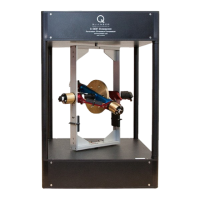
The Single Inverted Pendulum (SIP) system consists of a single rod mounted on a linear cart
whose axis of rotation is perpendicular to the direction of motion of the cart. As illustrated
in Figures 1, 2, 3, and 4, below, single pendulums come in two different lengths and can fit
on Quanser's IP01 or IP02 linear cart. Namely, there is a 12-inch-long "medium" pendulum
and a 24-inch-long "long" pendulum.
Both IP01 and IP02 are solid aluminum carts. They are driven by a rack and pinion
mechanism using a 6-Volt DC motor, ensuring consistent and continuous traction. Such cart
slides along a stainless steel shaft using linear bearings. The cart position is measured using
a sensor coupled to the rack via an additional pinion. Please review Reference [1] for a
complete description of both IP01 and IP02 systems.
However, it is reminded that, in the case of the IP01, a potentiometer is mounted on the axis
of rotation, thus allowing the measurement of the rod angle with the vertical axis. By oppo-
sition, the same rod angle is measured, on the IP02, by use of a quadrature incremental en-
coder.
Furthermore on the IP01, the "inverted" rod angle from the upright position is mechanically
constrained to ±32º. By contrast, on the IP02, the pendulum can be suspended in front of the
cart as free to rotate ±360º many times over, along the cart's axis of motion. This particular-
ity allows the IP02 to perform self-erecting and gantry experiments as well.
1.2. Inverted Pendulum Experiment: Control Challenge
This is the classic inverted pendulum example! As illustrated in Figures 1, 2, 3, and 4, be-
low, the objective of the single inverted pendulum experiments is to design a controller that
would balance the rod in the upright posture and track the cart to a desired position.
The ability to vary parameters and the hardware configuration is also available should you
wish to change the dynamics of the challenge. The system is supplied with a state-feedback
controller but, of course, you may design any other controller you wish. The complete
mathematical modelling and system parameters are provided to streamline the
implementation of the control theory of your choice.
Document Number: 511 ! Revision: 03 ! Page: 1