Orient conduit fitting so that
all portions of it clear the
edge of the knockout
Use washer (Grainger
#4DAX6)
between
conduit fitting and rear housing if
conduit fitting interferes with battery.
Figure-3
page 2
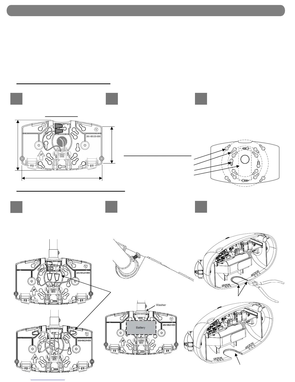
INSTALLATION and WIRING
1
2 3
On the mounting plate, remove the
round center knockout and the desired
pair of keyhole junction box knockouts.
Route leads through the center
opening and use code-approved
connectors to make the connections.
(See Wiring Diagram, page 3). Dress
wires and connectors inside junction
box. Units with Remote Lamp Wires:
If no remote lamps are connected,
remote lamp leads (+ and - low voltage
DC) should be left capped and dressed
in mounting plate as shown.
Taking care not to pinch wires or
connectors dressed inside junction
box, secure mounting plate to
junction box screws.
NOTE: To ensure proper
engagement of the mounting plate
latches to the housing, DO NOT
OVER-TIGHTEN THE SCREWS.
At upper center of the mounting plate,
remove the conduit connection
knockout. Also remove at least three
keyhole knockouts. Attach conduit and
secure mounting plate to wall surface
using fasteners with a minimum pullout
rating of 30 lbs. each.
See Wiring Diagram, page 3. Make
code-approved wire connections to
the AC power supply, and remote
lamps (if applicable). Dress wires
into slots so that the connectors are
secured as shown in Figure 2 or
Figure 3.
Remove U-shaped knockout from
top center of housing. Hint: Use a
pair of wire cutters first to start a cut
in the thick portion at each side of
the knockout, then finish breaking it
out with pliers.
JUNCTION BOX MOUNTING
-Some details shown below may vary-
CONDUIT SURFACE MOUNTING
NOTE: to avoid interference with components in the housing, use the most compact wire connectors appropriate to the wire gauge.
1
2 3
After knockout
removal
Cut
Secure wire connectors near the
center or near the upper latches
Figure-2
IMPORTANT: Provide each unit with a single-phase AC un-switched power supply from a circuit used for normal lighting.
“UVOLT” product versions operate from 120 volts through 347 volts. All other versions operate from 120 volts through 277 volts.
PRODUCT DAMAGE WILL OCCUR IF THE RATED INPUT VOLTAGE IS EXCEEDED.
NOTE: The battery must be connected to the charger board prior to applying AC power to the unit. Battery damage may occur if
the battery is connected longer than 24 hours without continuous AC power provided. See also “Important Battery Information”,
page 4.
NOTE: The maximum mounting height of ELM2L from ground is 11.7 feet, to meet the minimum illumination requirements of NFPA
101 (current Life Safety Code).
NOTE: Do not connect battery or power unit until remote units (if applicable) are fully connected and wires are isolated from other
potentials (i.e. remote wires shall be isolated from earth ground).
Mounting Plate:
7”
4-3/8”
3-1/4”
Junction boxes accommodated:
4” Square
4” Octagon
3-1/2” Round or Octagon
Single Gang Box