2.2.2 Sticks
There are two sticks on the transmitter and two preset modes for the functions of the sticks. You can
switch the sticks to suit your operation habit. For details, refer to section
4.4 Switching the Stick Modes
.
You can also loose or tighten the lever head to adjust the length of the stick.
2.2.3 Status Indicator
The status indicator is used to indicate the power and working status of the transmitter.
□
Off: the transmitter is powered off.
□
Lit in red: the transmitter is on and working.
□
Flashing: the transmitter is binding, switching the sticks or calibrating the middle position; or the
battery charge is low.
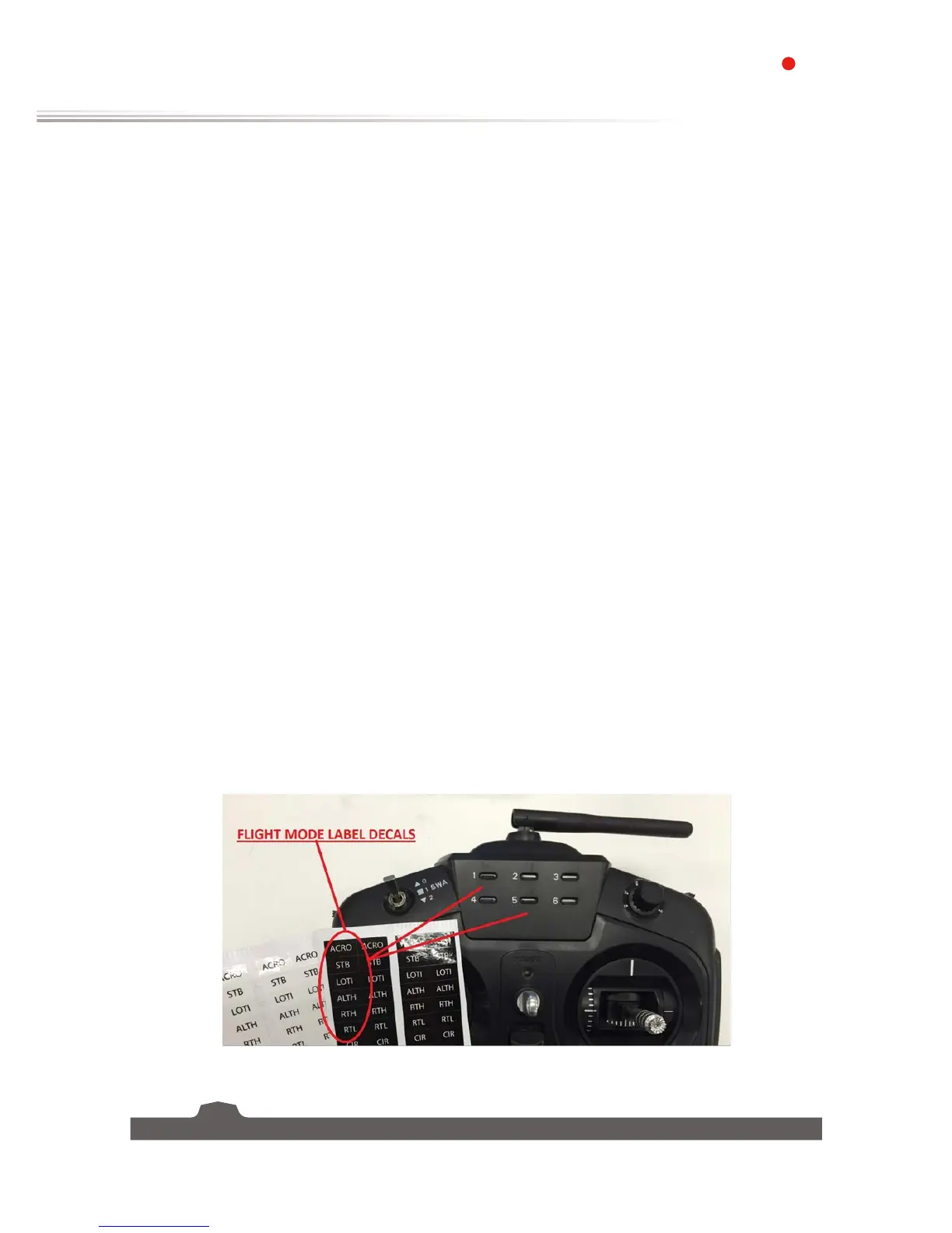
2.2.4 Channel 5 6 Position Knob
The Flight modes rotary knob has been specifically made to give a full 6 positions or flight modes by
simply rotating the knob. The 6 center mounted easily visible LEDs give a quick visual reference to the
selected flight mode/knob position. The included label sticker sheet lets you marks and layout your flight
modes to match your preferences.
The Flight modes knob is configured to channel 5 of the CPPM stream and corresponding CH5 PWM out
pins of the IA8 receiver. The 6 knob positions represent 6 different PWM/uS outputs that are spaced to
match most popular flight controller's flight mode options. The 6 PWM values for the knob positions are
as follows:
Channel 5 PWM to Knob position map:
Position 1 = 1200uS
2= 1300uS
3= 1400uS
4= 1500uS
5= 1700us
6= 1800uS