GV55W User Manual
TRA
CGV55WUM001 - 8 -
D
ATA_CABLE_W (Optional)
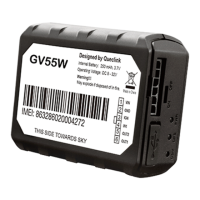
2.3. Interface Definition
G
V55W has a 6PIN interface connector. It contains the connections for power, and I/O. The
sequence and definition of the 6PIN connector are shown in the following figure:
F
igure 2. 6PIN Connector on GV55W
Table 4. Description of 6 PIN Connections
I
ndex
D
escription
R
emark
1
VIN
External DC power input, 12/24V
2
GND GND
3 IGN Ignition input, positive trigger
4
IN1 Digital input, negative trigger
5
OUT2 Open drain, 150mA max
6
OUT1 Open drain, 150mA max, with latch circuit
 Loading...