Do you have a question about the Queclink GL300W and is the answer not in the manual?
Lists documents referenced in the manual, including interface protocols.
Defines key abbreviations and terms used throughout the GL300W External Battery Kit User Manual.
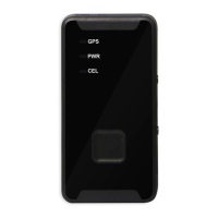
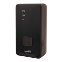
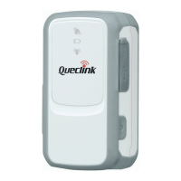
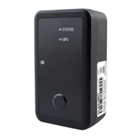
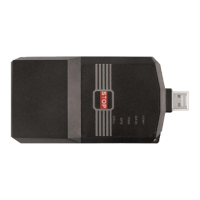
Visual presentation of the GL300W External Battery Kit components, including the tracker, PCU, and battery.
Details all components included in the GL300W External Battery Kit with their descriptions and images.
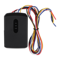
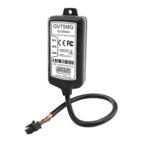
Introduces the Power Control Unit (PCU), its connectors, and onboard motion sensor functionality.
Describes the various interfaces available on the PCU for connectivity and data input/output.
Details the 4-pin connector for VBAT IN, specifying pin numbers and their functions for power input.
Explains the 8-pin connector's digital input pins used for monitoring external digital signals.
Configures Digital Input 1 as a lock switch, detailing its connection to toggle or reed switches.
Configures Digital Input 2 as a trigger switch, detailing its connection to tact or reed switches.
Describes the PWR Output interface, including UART for GL300W communication and power output pins.
Details the four toggle switches (SW101-SW104) on the PCU used for system configuration.
Explains SW101's function in enabling or disabling the onboard motion sensor.
Describes SW102's role in configuring the auto power-up function based on PCU rest status.
Details SW103's purpose in configuring the logical status of Digital Input 1.
Explains SW104's function in enabling or disabling the indication LED.
Explains the function of the Red LED for indicating power output status.
Describes the onboard motion sensor's operation, status reporting, and dependency on SW101.
Details how logical states of inputs and motion sensor affect PCU power output and reporting.
Lists the technical specifications of the GL300W External Battery Kit's high-capacity battery.
Provides instructions on how to charge the external battery using the provided AC-DC adapter.
Illustrates the physical connection setup between the external battery, PCU, and GL300W tracker.
Details the specific air protocol messages exchanged between the PCU and the backend server via GL300W.
Explains the format and parameters of the +RESP:GTLSW message for digital input 1 status changes.
Explains the format and parameters of the +RESP:GTTSW message for digital input 2 status changes.
Explains the format and parameters of the +RESP:GTOMS message for motion sensor status changes.
Explains the format and parameters of the +RESP:GTRST message sent periodically by the PCU.
The Queclink GL300W External Battery Kit (EBK) is a comprehensive accessory package designed to significantly extend the operational life of the GL300W GSM/GPRS/WCDMA/GNSS Tracker, making it suitable for specialized applications such as container tracking. This kit comprises an external battery, a Power Control Unit (PCU), and a rugged Pelican 1020 waterproof casing, all working in conjunction to enhance the tracker's functionality and durability.
The core function of the GL300W EBK is to provide an extended power source for the GL300W tracker, thereby increasing its standby and operational time. The PCU acts as the central management unit for power, intelligently drawing energy from the external battery. Beyond simple power delivery, the PCU integrates advanced features, including an onboard motion sensor and external digital inputs, which contribute to the kit's versatility and intelligent power management.
The GL300W EBK is designed for ease of integration and flexible deployment. The Pelican 1020 waterproof casing, built to IP67 standards, ensures robust protection for the internal components, including the GL300W tracker, PCU, and external battery, against environmental elements. This makes the kit ideal for outdoor and harsh conditions where standard trackers might fail.
The PCU features two main connectors: a 4-pin connector for the VBAT IN interface, which connects to the external battery, and an 8-pin connector for Digital Input and PWR Output interfaces. These interfaces allow for a range of external interactions and configurations.
The digital input interface includes two digital inputs that can be used to monitor external digital signals. These inputs are highly configurable and can be connected to various types of switches, such as toggle switches, tact switches, or reed switches, depending on the application's needs. Digital input 1 functions as a lock switch, and its logical status directly influences the power output of the PCU. This allows for conditional power management, where the GL300W tracker can be powered on or off based on the state of an external switch or sensor. For instance, if connected to a reed switch, the tracker could be activated or deactivated based on the opening or closing of a container door. The logical status of digital input 1 can be configured via toggle switch SW103 on the PCU, allowing users to define whether a high or low electrical level corresponds to a '0' or '1' logical state.
Digital input 2 serves as a trigger switch, also recommended for connection to tact or reed switches. Its default logical status is '0' and reverses when the electrical level changes twice. Similar to digital input 1, the logical status of digital input 2 also affects the power output of the PCU, providing another layer of control over the GL300W's power state.
The PWR Output interface provides power to the GL300W tracker and includes a UART interface for communication between the GL300W and the PCU. This communication enables the PCU to send reporting messages to the backend server via the GL300W, detailing changes in logical status or motion.
The PCU incorporates an onboard motion sensor, which can be enabled or disabled using toggle switch SW101. When enabled, the motion sensor detects whether the PCU (and thus the GL300W) is in motion or at rest. The logical status of the motion sensor (1 for motion, 0 for rest) plays a crucial role in the PCU's power output decisions. There is a five-minute delay after the motion sensor changes from '1' to '0' before the power output is affected, ensuring that brief periods of rest do not immediately shut down the tracker.
The relationship between the logical statuses of digital input 1, digital input 2, and the motion sensor determines when the PCU enables or disables power output to the GL300W. The power output can only be disabled when both digital input 1 and digital input 2 are in a '0' logical state. This intelligent power management ensures that the tracker operates only when necessary, conserving battery life. The PCU also reports any changes in these logical statuses to the backend server through the GL300W, providing real-time insights into the kit's operational state.
The PCU features four toggle switches (SW101 to SW104) for configuration. SW101 enables/disables the onboard motion sensor. SW102 configures the auto power-up function; when set to 'L', power output is enabled for at least 5 minutes daily, even at rest, while 'H' prevents power output when at rest (if both digital inputs are '0'). SW103 configures the logical status of digital input 1. SW104 enables/disables the indication LED, which lights up only when power output is enabled.
The GL300W EBK supports various reporting messages to the backend server via the GL300W. The +RESP:GTLSW message is sent when the logical status of digital input 1 changes, providing information on the SW103 status and the logical state of digital input 1, along with GPS and device data. Similarly, the +RESP:GTTSW message is sent upon a change in the logical status of digital input 2. The +RESP:GTOMS message is transmitted when the motion state changes (due to the motion sensor or SW101 state), indicating whether the motion sensor is enabled/disabled and its current state (rest, movement, or initial status). Additionally, if SW102 is set to 'L', the PCU sends a +RESP:GTRST message every 24 hours, providing regular status updates.
Charging the external battery is a straightforward process. The kit includes an AC-DC power adapter specifically for this purpose. The external battery has two connectors: one for power output to the PCU and another dedicated for charging. It is crucial to remove the PCU from the external battery before charging. The charging process is indicated by an LED on the adapter, which glows red during charging and turns green when the battery is fully charged. A full charge typically takes approximately 16 hours. This clear indication and dedicated charging port simplify battery maintenance, ensuring the kit is always ready for deployment.
| GSM Frequency | 850/900/1800/1900 MHz |
|---|---|
| GPRS | Class 12 |
| GPS Sensitivity | -165 dBm |
| Charging Voltage | 5V DC |
| Certifications | CE, FCC, RoHS |
| Operating Temperature | -20°C to +55°C |
| Storage Temperature | -40℃ ~ +85℃ |
| GPS Chipset | MTK |
| TTFF (Open Sky) | Hot start: 1s |
| Antenna | Internal |
| Accelerometer | Yes |
| Water Resistance | IP65 |
| Communication Protocol | TCP, UDP |
| Interface | USB |
| Location Accuracy | 2.5m CEP |