Do you have a question about the Queclink GV600MG and is the answer not in the manual?
Lists related documents for GV600MG protocol.
Defines key terms and abbreviations used in the manual.
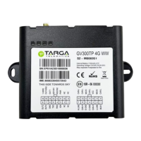
Details different GV600ME product models and their specifications.
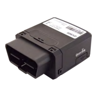
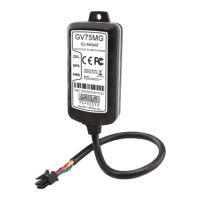
Lists the physical components and optional accessories for the GV600MG.
Defines the 18-pin interface connector and its pin assignments.
Explains the wire color coding for the standard GV600MG cable.
Instructions for opening and properly sealing the device casing.
Step-by-step guide for inserting the SIM card into the device.
Information on installing the internal backup Li-ion battery.
How to connect the device to vehicle power sources (12V/24V).
Configuration and connection for vehicle ignition detection.
Details the four digital inputs and their electrical characteristics.
Describes the single analogue input and its voltage range.
Explains the four digital outputs and their current limits.
Defines the meaning of device status and LED indicators.
Explains how to connect a temperature sensor to the device.
Details the serial port (TXD/RXD) for TTL communication.
| GPRS | Class 12 |
|---|---|
| GPS Channels | 72 |
| GPS Sensitivity | -167 dBm |
| Tracking Sensitivity | -165 dBm |
| Acquisition Sensitivity | -148 dBm |
| AGPS | Supported |
| Internal Memory | 16 MB |
| Digital Outputs | 1 |
| Analog Inputs | 1 |
| Serial Interface | RS232 |
| Bluetooth | Bluetooth 4.0 |
| Storage Temperature | -40 to +85 °C |
| Humidity | 5% ~ 95% RH |
| GSM | 850/900/1800/1900 MHz |
| GNSS | GPS, GLONASS |
| Location Accuracy | 2.5 m |
| TTFF (Open Sky) Hot start | <1s |
| Accelerometer | Yes |
| Antenna | Internal GSM and GPS antenna |
| Certifications | CE, FCC, RoHS |
| Operating Voltage | 9~36V DC |
| GPS Chipset | u-blox M8 |