EasyManuals Logo

Queclink GV600MG User Manual

Queclink GV600MG
21 pages
To Next Page IconTo Next Page
To Previous Page IconTo Previous Page
Page #9 background imageLoading...
Page #9 background image
GV600MG User Manual
QSZTRACGV600UM0106 4
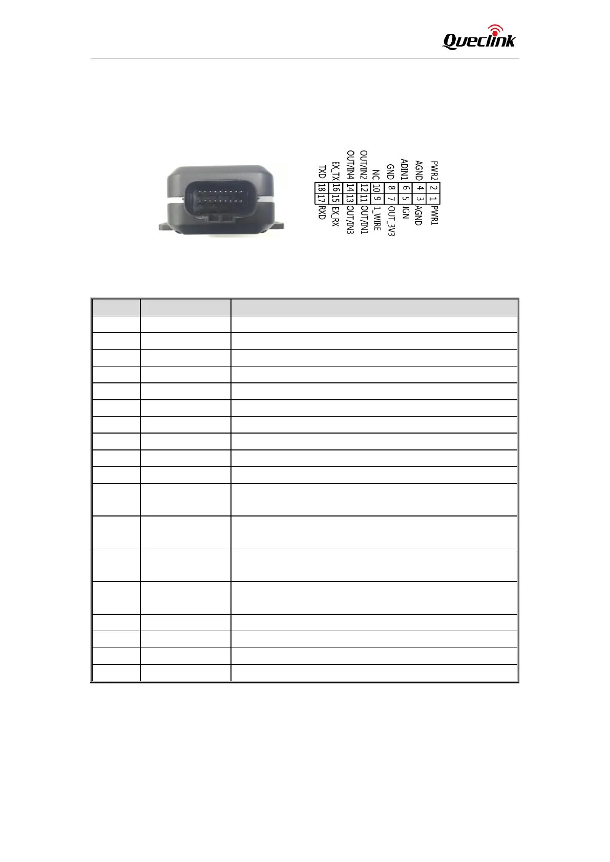
2.3. Interface Definition
The GV600MG Tracker has an 18-pin interface connector which contains the connections for
power, I/O, TTL, etc. The sequence and definition of the 18-pin connector are shown in the
following figure:
Figure 1. The 18-pin Connector on the GV600MG
Table 5. Description of 18-pin Connections
Index
Description
Comment
1
PWR1
Primary Power 8-32V
2
PWR2
Secondary Power 8-32V
3
AGND
Primary Analogue Ground
4
AGND
Secondary Analogue Ground
5
IGN
Ignition Detection Input, Positive Trigger
6
ADIN1
Analogue Input 0-32V
7
OUT_3V3
External Accessory Power 400mA Max
8
GND
External Accessory Ground
9
1_WIRE
Temperature Sensor Input
10
NC
NC
11
OUT/IN1
Negative trigger input1 for normal use or
Open drain output1 150mA max drive current
12
OUT/IN2
Negative trigger input2 for normal use or
Open drain output2 150mA max drive current
13
OUT/IN3
Negative trigger input3 for normal use or
Open drain output3 150mA max drive current
14
OUT/IN4
Negative trigger input4 for normal use or
Open drain output4 150mA max drive current
15
EX_RX
UART RXD RS232
16
EX_TX
UART TXD RS232
17
RXD
UART RXD TTL
18
TXD
UART TXD TTL

Questions and Answers:

Question and Answer IconNeed help?

Do you have a question about the Queclink GV600MG and is the answer not in the manual?

Queclink GV600MG Specifications

General IconGeneral
BrandQueclink
ModelGV600MG
CategoryGPS
LanguageEnglish

Related product manuals