5G Module Series
5G-REDCAP_EVB_User_Guide 23 /
46
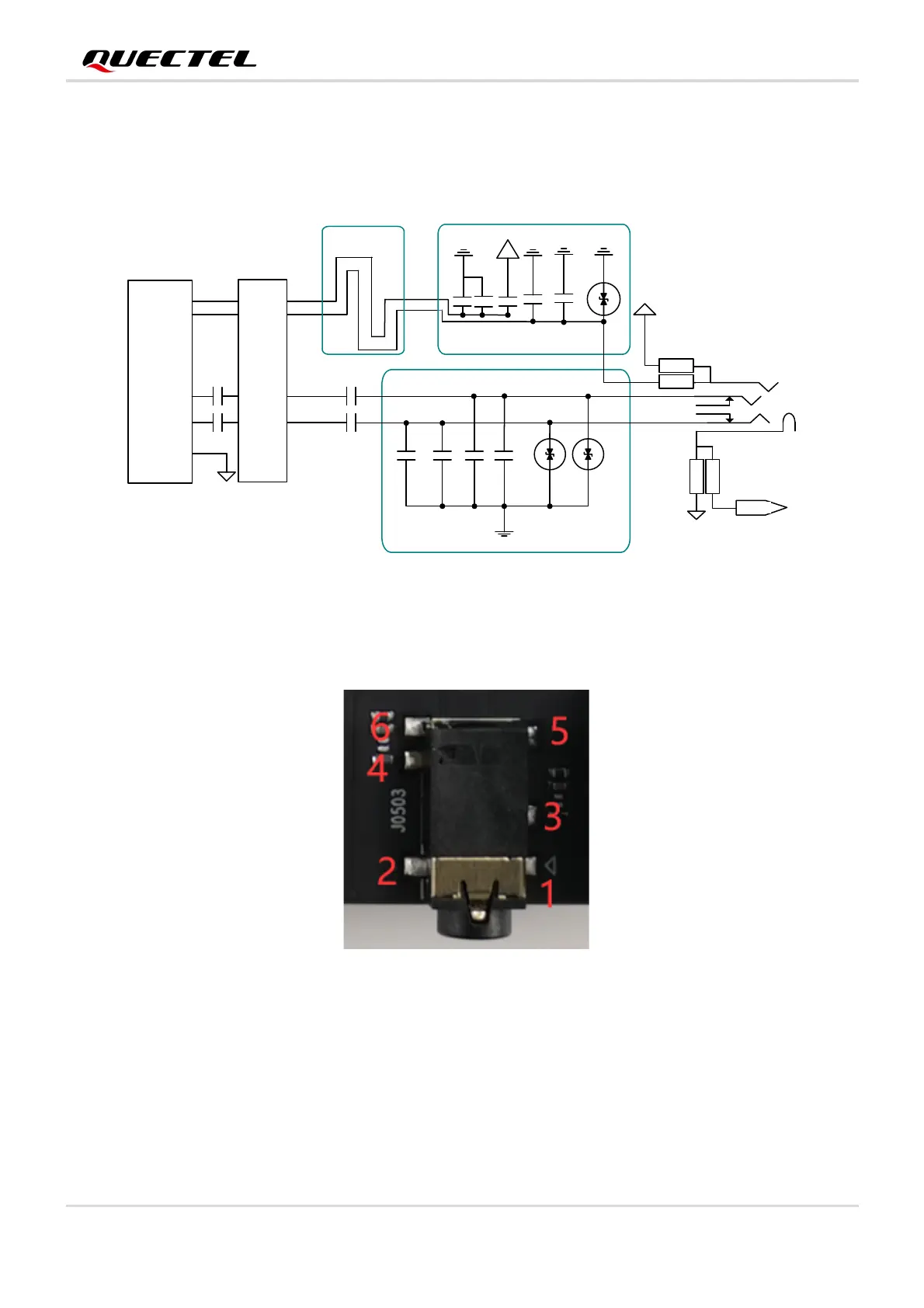
3.4.1.2. Earphone Application
Audio interface is designed for earphone. A reference circuit design is shown by the following figure.
Figure 14: Reference Circuit Design for Earphone Application
The figure and table below illustrates the pin assignment and pin definition of earphone connector.
Figure 15: Pin Assignment of J0503
SP K_L
MIC_N
MIC_P
75pF
GND GND
AG ND
Close to Socket
Differential layout
15pF
10pF
33pF
GN D
GND
AG ND
Codec
Close to Socket
AG ND
ES D
ES D
Audio Jack
22uF
J0503
1
4
5
3
2
SP K_R
10pF
33pF
22uF
6
MIC_P
0R
NM_0R
33pF
GND
AG ND
0R
NM_0R
10pF
4.7uF
BTB CON
J0502
1uF
1uF