LTE Standard Module Series
EC21_Series_Hardware_Design
53
/ 118
CTS 64 DO DTE clear to send signal from DCE
RTS 65 DI
DTE request to send signal from
DCE
DTR 66 DI
Data terminal ready,
sleep mode control
1.8 V power domain.
Pulled up by default. Driving it
low can wake up the module.
If unused, keep it open.
TXD 67 DO Transmit
1.8 V power domain.
If unused, keep them open.
RXD 68 DI Receive
Table 13: Pin Definition of Debug UART Interface
Pin Name Pin No. I/O Description Comment
DBG_TXD 12 DO Debug UART transmit
1.8 V power domain
If unused, keep them open.
DBG_RXD 11 DI Debug UART receive
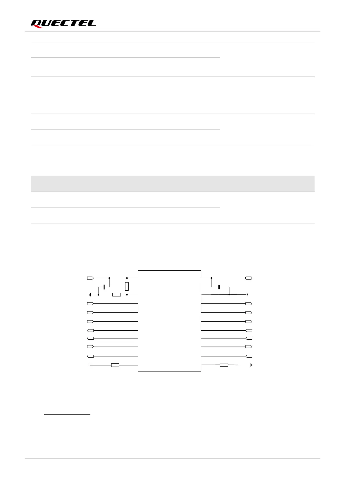
The module provides 1.8 V UART interface. A voltage-level translator should be used if customers’
application is equipped with a 3.3 V UART interface. A voltage-level translator TXS0108EPWR provided
by Texas Instruments is recommended. The following figure shows a reference design.
VCCA VCCB
OE
A1
A2
A3
A4
A5
A6
A7
A8
GND
B1
B2
B3
B4
B5
B6
B7
B8
VDD_EXT
RI
DCD
RTS
RXD
DTR
CTS
TXD
51K
51K
0.1uF
0.1uF
RI_MCU
DCD_MCU
RTS_MCU
RXD_MCU
DTR_MCU
CTS_MCU
TXD_MCU
VDD_MCU
Translator
10K
120K
Figure 20: Reference Circuit with Translator Chip
Visit http://www.ti.com for more information.
Another example with transistor translation circuit is shown as below. For the design of circuits in dotted
lines, please refer to that of circuits in solid lines, but please pay attention to the direction of connection.