M20 EVB User Guide
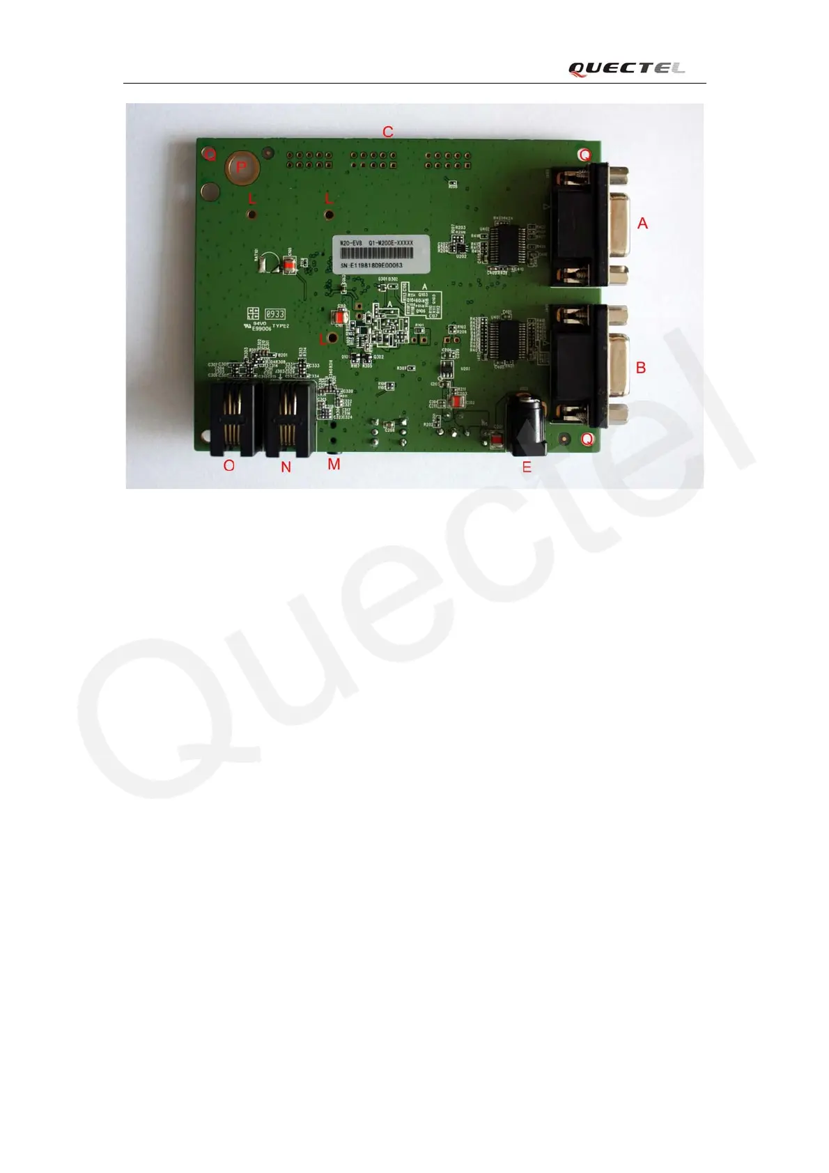
Figure 2: EVB bottom view
A: Serial port 1
B: Serial port 0
C: Test points
D: SIM card socket
E: Power adapter interface
F: Module operating status indication LEDs
G: PWRKEY button
H: EMERG_OFF button
I: 5V switch
J: VCHG switch
K: Download switch
L: Screw holes for fixing the M20 module
M: Headset socket
N: Handset socket of audio channel 2
O: Handset socket of audio channel 1
P: Antenna connector fixing hole
Q: Screw holes for EVB placement
R: Connector for M20 module
M20_EVB_UGD_V1.01 - 9 -