6
QUEST 506 INSTALLATION, OPERATION AND MAINTENANCE INSTRUCTIONS
QUESTCLIMATE.COM(877) 420-1330
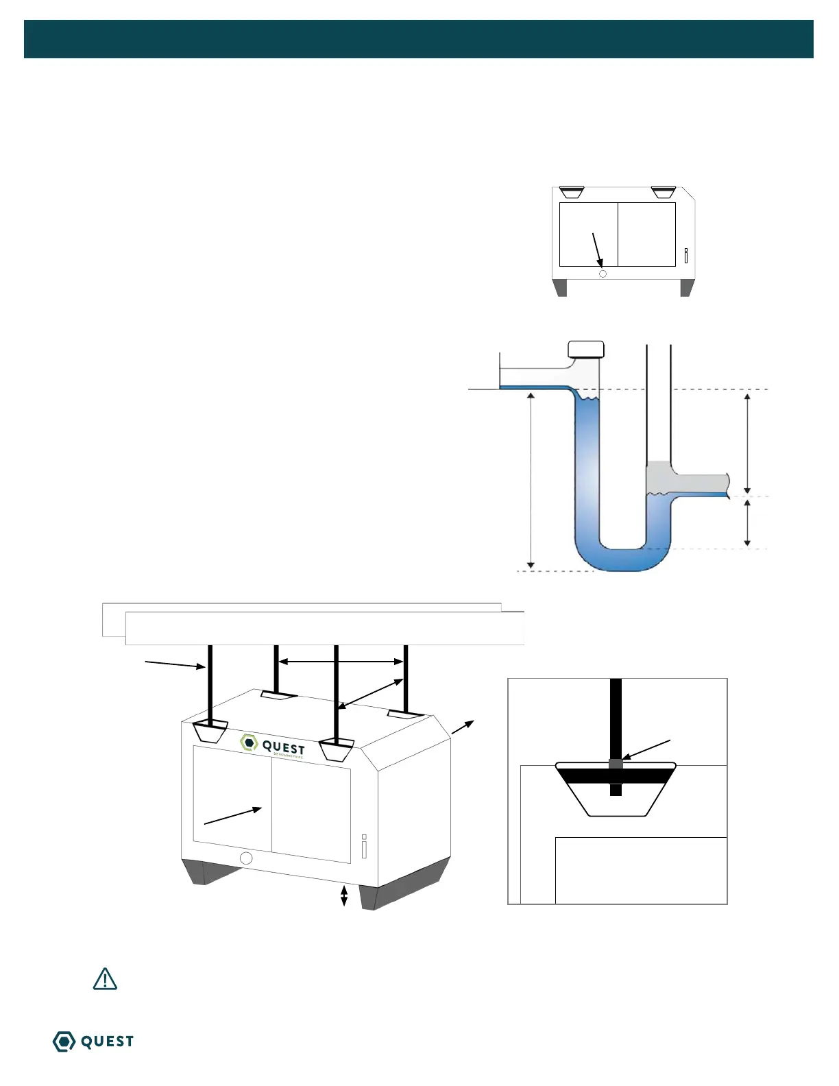
4.3 CONDENSATE WATER REMOVAL
Condensate drains by gravity via the drain port. Use 3/4” male NPT PVC pipe. An optional
condensate pump kit may be installed if a lift is required to dispose of the condensate. Optional parts
list for information on the kit.
FOLLOW DIAGRAM:
• Level within 2°
Vent:
• Place vent after the trap.
• Vent should be open.
• Height of vent should be higher than drain outlet.
Cap:
• A clean out can be placed before trap but must be
sealed with a cap.
Drain Line:
• Drain line should go in a downward slope to the drain.
• 1/4” drop per foot.
4.4 HANGING DIAGRAM
PARTS NEEDED: 4 pieces 3/8” threaded rod (not included)
4 - 3/8” threaded jam nuts (not included)
WARNING! Hanging installation must meet all state and local codes.
28.95
27.25
3/8” threaded rod
Intake Air
Treated Air
3/8” Jam Nuts
5.56”
Drain Trap Configuration
VENT OPEN
CAP
2”
6.75”
4”
3/4” drain port