31
VII. INTRODUCTION TO THE MODEL OB-100.
The Quest Model OB-100 Octave Filter is a plug-in module containing a
selectable set of filters. The OB-100 meets the most stringent requirements
of ANSI S1.11-1986 and IEC R225-1966 for octave band filters. The unit
contains ten selectable filter ranges from 31.5 Hz to 16 kHz center
frequencies with full octave band width.
Primary uses include frequency analysis for product noise emission, material
acoustics, community noise, audiometer calibration and analysis of
audiometric rooms. Active filters are employed throughout the Model OB-100,
thus permitting the unit to have both high accuracy and compact size.
VIII. ABOUT THE FILTER
A. Filter Controls
POWER Switch
A three position slide switch that does the following:
OFF -- Disconnects the filter circuitry from the attached sound
level meter. With this switch in the off position, the OB-100 does
not use power from the meter batteries.
MANUAL -- Filter frequency selection is performed with two push
buttons (START Buttons).
AUTO -- Unit automatically cycles through the desired filter
frequencies while storing sample information for each frequency
during the RUN mode.
START Buttons
Allow the user to cycle through the different bandpass filters. The two
buttons allow manual frequency control (in MANUAL Mode) or frequency
direction control (in AUTO Mode).
-20 dB Button
When this button is depressed, the output of the filter is amplified by
exactly 10 times (20 dB) and then fed back to the sound level meter.
Therefore, 20 dB has to be subtracted from the meter reading when using
this button.
TIME
A screwdriver adjustment to control the automatic cycle time of each
filter frequency from approximately 5 to 30 seconds.
32
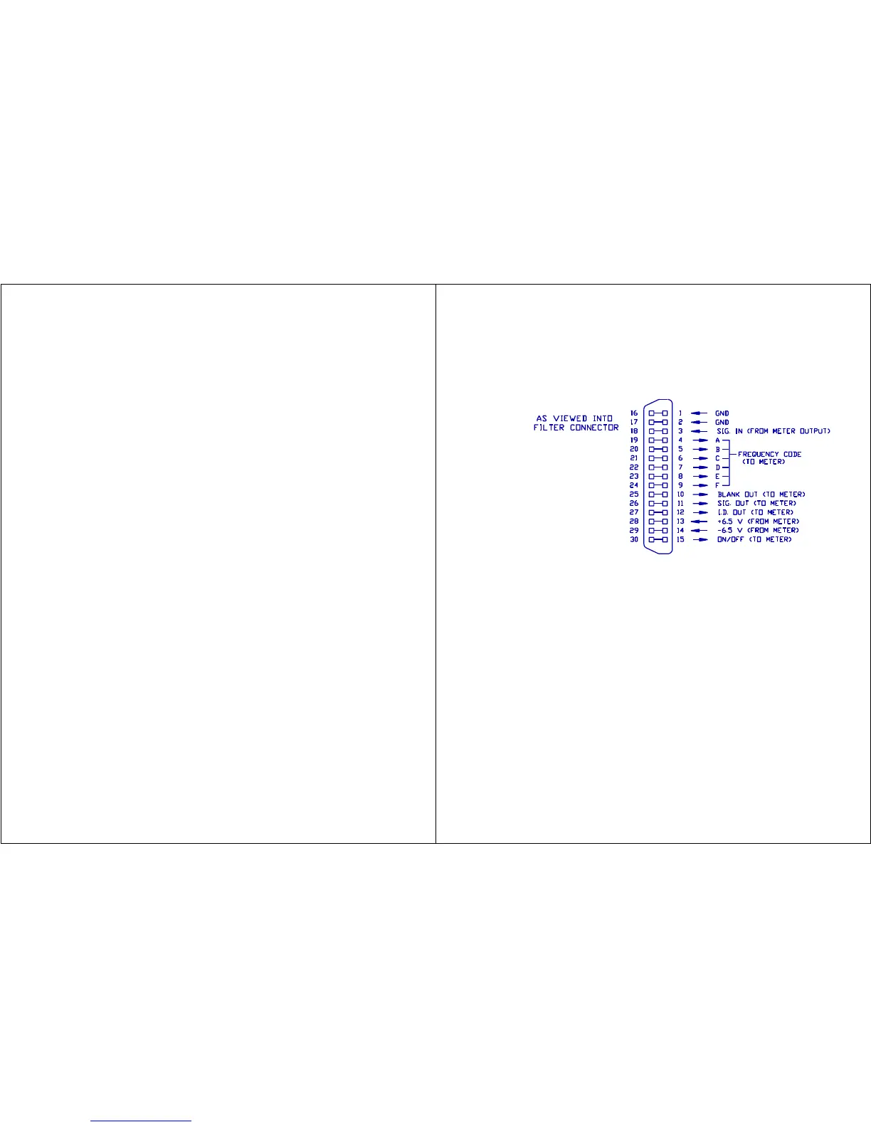
Figure 23. OB-100 External Filter Connector
(Located on Meter Bottom)
B. Filter Connector
The 30 pin connector on the top of the filter is used for connecting the
filter to the sound level meter. Figure 23 shows the pinout for the filter
connector.
IX.
GENERAL
OPERATING
PROCEDURE
The Model
1800-100
Octave
Band
Analyzer
is made up
of the
Model 1800
Precision
Impulse
Integratin
g Sound
Level
Meter and
the OB-100
Octave
Filter
Set. The
two units
are
connected together with the long captive screw provided with the filter box.
The General Operating Considerations for the Model 1800 (Section IV) are
basically the same when using the Model OB-100 with the meter.
A. Operational Check
The Model 1800 should be calibrated as outlined in the meter section of the
manual (Section III, B, Calibration) while the OB-100 is OFF. The OB-100 has
a fixed input to output voltage ratio of approximately 1 (0 dB) at each
center frequency and requires no adjustment. After the meter is calibrated,
check the filter for proper operation as follows: