coupler and the coupler rests flush on the inner rim of the calibrator. Turn the
calibrator on and push down the SOUND LEVEL key on the MICRO-15. The
MICRO-15 should display correctly.
Atmospheric pressure has virtually no effect on the MICRO-15. However,
calibrator sound levels are affected by altitude; and if the MICRO-15 is calibrated
at high altitudes, corrections must be made. For the Quest Calibrator the
correction is -.1 dB for each 2000 feet above sea level.
4. If the reading is off slightly, insert a small screwdriver in the hole marked
CAL and slowly turn the adjustment screw until the display reads correctly.
5. The MICRO-15 is now calibrated and ready for use.
6. If a calibrator is used at any frequency other than 1000 Hz, then the
proper correction for that frequency weighting must be made (see Figure 4).
OPERATING PROCEDURE
1. If display is blank press ON/OFF to turn unit on.
2. Clear the MICRO-15 memory by pressing and holding down both the
ON/OFF key and the PAUSE key for five seconds until the display shows a
single zero and a single colon.
3. If 2 decimal points and a colon are displayed replace the battery and
continue.
4. Check the calibration of the unit. (See preceding section, Calibration and
Maintenance.)
5. Check code to see that it is correct. (See Setting Internal Switches and
Code Setup Procedures in following pages.)
6. Attach the microphone to the collar of the operator (see Effects of
Operator's Presence in following paragraph).
7. Press the RUN key.
8. Install the security cover and attach the unit to the operator's belt or
pocket.
9. At the end of the workday, remove the security cover and press PAUSE.
10. Remove the unit from the operator.
11. Press each function key and record the results or connect a printer to
the printer jack and press PRINT.
12. Press and hold the ON/OFF key until the display becomes blank. If the
unit is not going to be used for several days, remove the battery.
Effects of Operator's Presence
Any object or surface can act as a reflector or absorber of sound. An
operator or person wearing the dosimeter is also a reflector or absorber of sound
and affects the microphone performance. The MICRO-15 is designed to read
correctly with the microphone in a random incidence sound field without the
presence of reflecting objects.
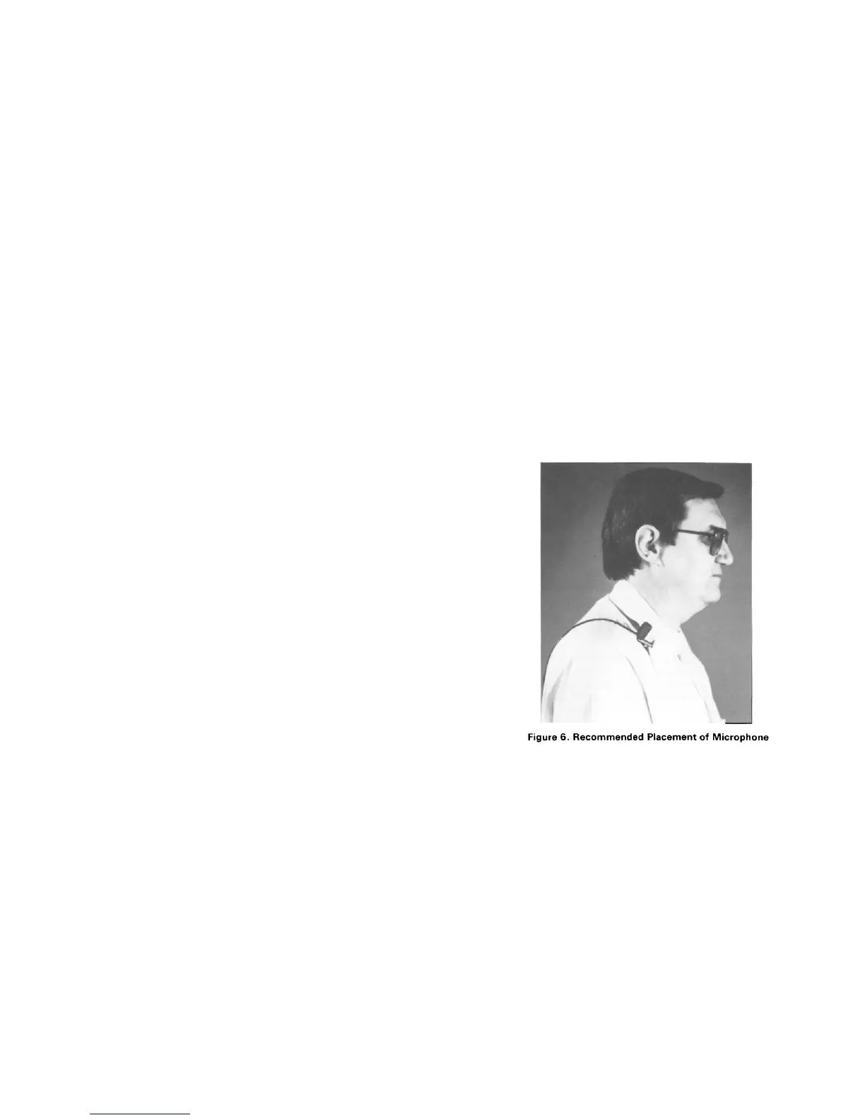
The recommended placement of the microphone for personal noise
monitoring is on the shirt collar, high on the shoulder, and away from the neck as
far as practical (see Figure 6). If the noise is directional it is generally the best
practice to place the microphone near the ear which receives the most noise
exposure.
If the MICRO-15 is to be used as a hand held instrument the microphone
should be mounted on the 58-863 microphone boom (see Figure 7). It may be
either clipped to the boom or the clip removed and the microphone screwed to
the boom. The boom is then attached to the belt clip on the back of the
instrument. If desired the complete