EN
BTQ110-125 INSTALLATION AND USE MANUAL - IT EN - REV004A
19
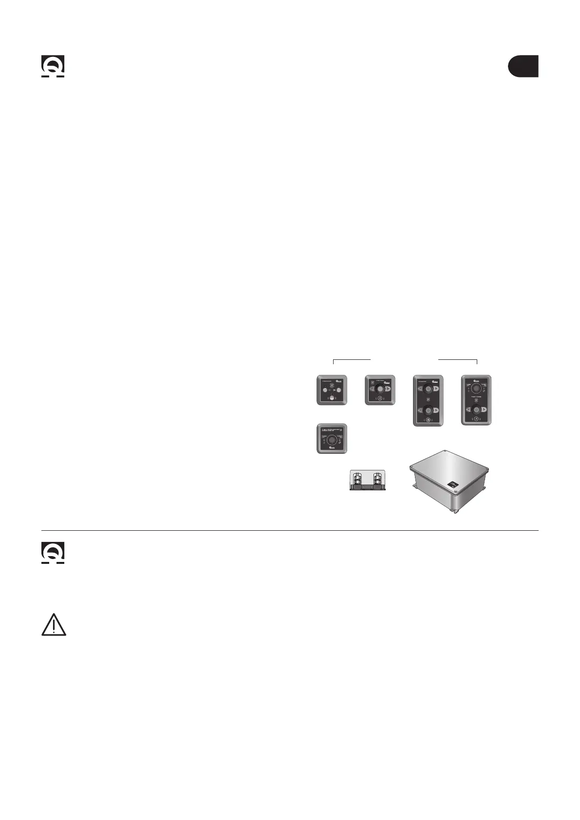
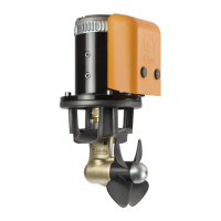
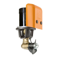
2 - Supplied parts BTQ110/125
2.0 - Package contains the following parts
• Thruster
• Drill template
• Gasket
• O-ring (for assembly)
• Installation and use manual
• Conditions of warranty
2.1 - Tools needed for installation
• Drill and drill bits Ø 6 mm (15/64”)
• Hollow mill Ø 25 mm (1”)
• hexagonal male key 4 mm, 5 mm and 6 mm
• Fork or polygonal key 10 mm
TSC THRUSTER
MAIN SWITCH
COMMAND
TFH3 FUSEHOLDERS
TMS THRUSTER MAIN SWITCH
CONTROL PANELS
STERN
BOW
TCD 1022 TCD 1042 TCD 1044 TCD 1062
3 - Safety BTQ110/125
2.2 - Quick
®
accessories for activation
of the retractable thruster
• Remote control TCD 1022
• Remote control TCD 1042
• Remote control TCD 1044
• Remote control TCD 1062
with integrated line switch control
• Thruster main switch command TSC
• Thruster main switch TMS
• THF3 fuseholders
3.0 - Warnings
• Quick
®
Thrusters have been designed and constructed only for nautical use.
• Do not use these appliances for other uses.
• Quick
®
shall accept no responsibility for direct or indirect damages caused by improper use of the appliance or an
improper installation.
• The Thruster is not designed to maintain loads generated in particular atmospheric conditions (storms).
• We recommend you entrust preparation and positioning of the tube on the hull to a skilled professional. These are
generic instructions and do not give details of the preparatory operations for installing the tunnel, since this is the
competence of the boatyard. The installer shall bear full responsibility for any problems caused by defective instal-
lation of the tunnel.
• Do not install the electric motor near easily inammable objects.