EN
BTQ110-125 INSTALLATION AND USE MANUAL - IT EN - REV004A
23
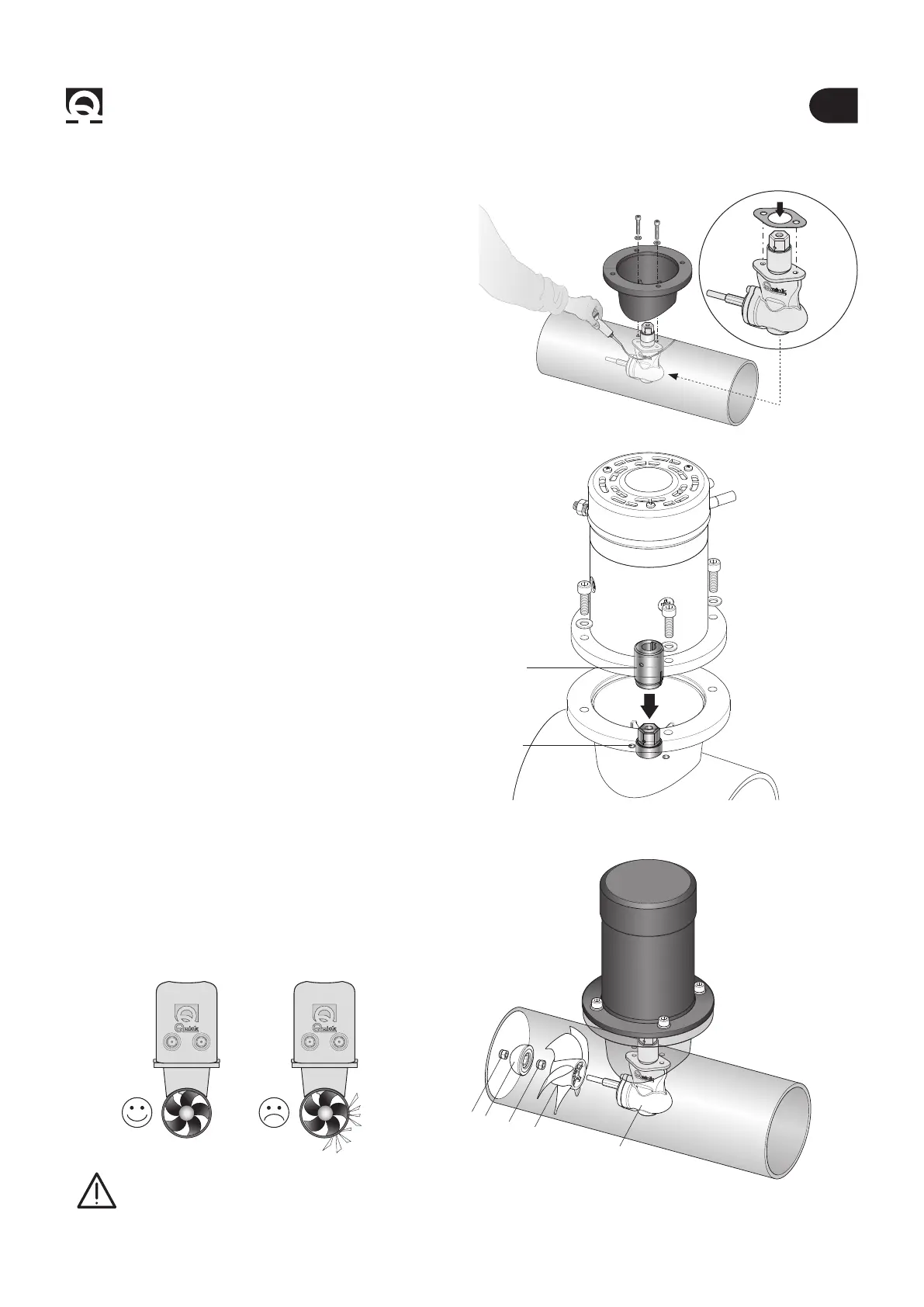
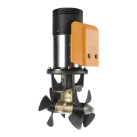
BTQ110/1254 - Installation
4.3 - Gearleg and motor support ange
• Assemble the motor on the ange by joining
the two elastic coupling halves.
Fasten it with the provided 4 screws and washers.
• Proceed with tting the gearleg with the special seal
gasket.
• For further protection against the entry of water, apply
silicone for nautical use around the point of contact be-
tween ange and tube.
• Fasten everything to the ange using the special screws
and washers.
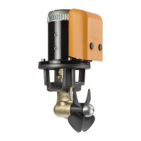
• Insert the propeller A in the gearleg B, x the propeller
with the self-locking nut C, insert anode D and lock it with
the other self-locking nut C.
A
C
C
D
B
4.4 - Propeller tting
WARNING: on conclusion of assembly, make
sure that the propeller is exactly positioned at
the central point of the tunnel.
ELASTIC
COUPLING
ELASTIC
COUPLING
SILICONE