33
INSTALLATION
GB
CHC1202M IT GB - REV005B
11
3
3
22
Max. 10 mm
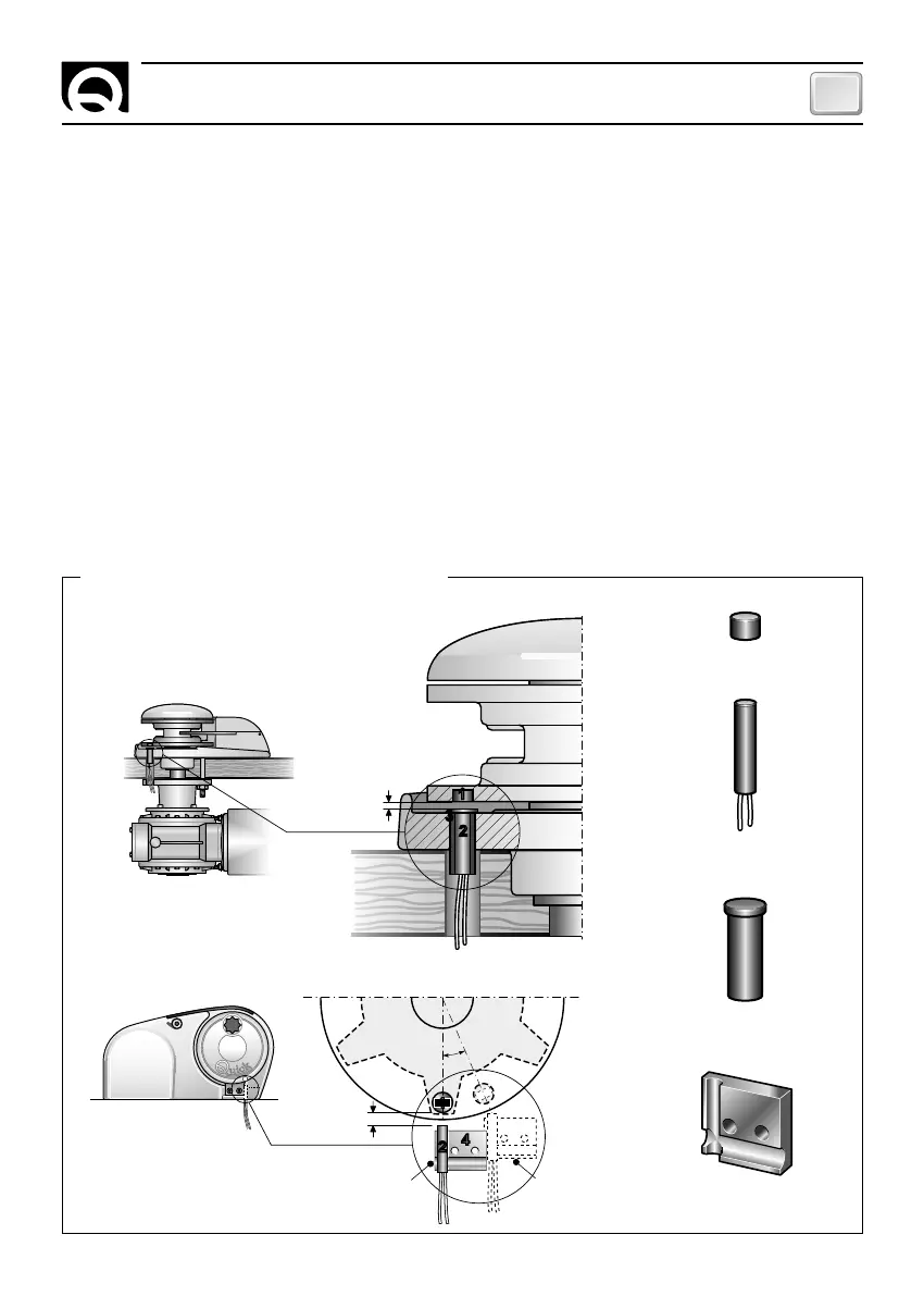
EXAMPLES OF LAPS SENSOR INSTALLATION
22
44
2
2
22
Max. 10 mm
11
± 20°
horizontal windlasses
vertical windlasses
INSTALLING THE LAPS SENSOR
Chain counter installation takes place in three steps: installation of the laps sensor on the windlass,
mounting of the chain counter and electrical connections.
Quick
®
windlasses
All Quick
®
windlasses come with a laps sensor suitable for use with chain counter CHC 1202 M.
Other windlasses
In order for the chain counter to measure the exact length of the chain, it has to count the number of rev-
olutions completed by the gear that drives the chain (gypsy). A laps sensor kit is supplied with the chain
counter. This kit includes a cylindrical magnet, a magnetic field sensor and two plastic adaptors to be used
to secure the sensor in place. The magnet is to be secured to the gypsy while the magnetic sensor is to be
fixed to the windlass base.
The standard installation procedure is described below. Unfortunately we cannot describe a procedure ap-
plicable to all types of situation. Adapt this procedure to satisfy your own individual requirements.
MAGNET
SENSOR
ADAPTOR
ADAPTOR
1
2
3
4
Ideal
installation
Maximum
removal