CHAIN COUNTER OPERATION
MAIN WINDOW
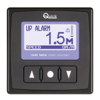
Once the initialization procedure has been completed, the main window is displayed:
This window is divided into the following sections:
Count line The length of the chain lowered is shown in this area.
Measure unit area The unit of measurement currently being used is shown in this area. The values may be dis
-
played in "M" for meters and "FT" for feet.
State line Messages regarding the state of the chain counter or faults detected are shown here.
Icon area The icons regarding the state of the chain counter or faults detected are shown here.
Monitor line The following information may be displayed here, depending on the selections made by the
user: supply voltage and chain speed.
STOP
SPEED 0M/M
State line
Count line
Icon area
Measure unit area
Monitor line
CHAIN COUNTER OPERATION
Three elements are employed between user and counter interface:
A GRAPHIC DISPLAY, CONTROL KEYS AND BUZZER.
The graphic display screen shows the measure of chain lowered, state of the chain
counter along with other information.
The control keys comes with three keys. The two side keys are used to move the
anchor up (
p
,UP key) or down (
q
,DOWN key), move within the system menus or
modify the value of parameters.
The middle key (
=
SELECT) is used to select the monitoring mode, go to the sys-
tem menus or confirm parameters.
The buzzer signals when the keys have been pressed or when it is necessary to
call the user's attention. Use the switch on the power supply line to turn the chain
counter on and off.
When the chain counter is turned on, the following window is displayed for a few
seconds:
Where XXXXX is the serial number, YY is the week of production and ZZ is the year
the chain counter was produced.
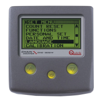
When the chain counter is turned on the first time, the menu used to select the lan
-
guage in which messages are displayed appears.
The selected language can be changed later on.
CHC1203
S/N : XXXXX/YYZZ