20 FUM5-00AM-DES-N5550 V1.0 / 31.01.2019
en - Operating and Installation Instructions Q node 5
Correct disposal of this product
Products delivered in Germany and directly from Germany
All appliances must be brought to a controlled recycling
SODQW'XHWRJRYHUQLQJUHJXODWLRQV
electrical and electronic devices from QUNDIS must not be dis-
posed of via public collection points for electrical devices. All old
electronic devices from QUNDIS must be sent to us for disposal.
The stamped delivery is to be sent to the following address:
481',6*PE+
6RQQHQWRU 7HO
(UIXUW )D[
*HUPDQ\ 0DLOLQIR#TXQGLVFRP
QUNDIS ensures correct disassembly and recycling of the devices. Costs for disposal are borne by QUNDIS.
$OWHUQDWLYHO\GLVSRVDOE\FXVWRPHUVLVSRVVLEOHZLWKUHJDUGWRWKHVSHFL¿HGZDVWHFRGHQXPEHUYLDSULYDWHZDVWHGLVSRVDOFRQWUDFWRUVDW
WKHLURZQH[SHQVH
In countries of the European Community excepting Germany
Information concerning correct waste disposal is available from your dealer or from the responsible sales and distribution channels.
Start of service life calculation with a new battery:
$IWHUWKHQHWZRUNQRGHKDVEHHQ¿[HGLQSODFHWKHEDWWHU\SOXJFRQ-
QHFWRULVLQVHUWHGLQWRWKHSOXJFRQQHFWRUSURYLGHG7KHQHWZRUN
node display reads
. The operator then has to press the blue
',63/$<EXWWRQRQFHLQRUGHUWRVWDUWWKHVHUYLFHOLIHFDOFXODWLRQIRU
the new main battery.
Caution: It is possible to disconnect the main battery from the net-
work node during operation and then to insert the connector again.
,Q WKLV FDVH GR QRW FRQ¿UP E\ SUHVVLQJ WKH ',63/$< NH\ ± WKLV
would result in the wrong remaining capacity display.
Changing the battery: :KHQ D ÀDW PDLQ EDWWHU\ LV UH-
SODFHG WKH ROG EDWWHU\ LV UHPRYHG ¿UVW DQG WKHQ WKH QHZ RQH
is inserted. The operator then has to wait until
is dis-
SOD\HG DQG WKHQ SUHVV WKH EOXH ',63/$< EXWWRQ RQFH LQ RU-
der to start the service life calculation for the new main battery.
The backup battery must not be disconnected at this point
since this would result in a loss of data.
Depassivation::KHQWKHPDLQEDWWHU\LVVWRUHGIRUORQJHUSHULRGV
SDUWLFXODUO\DWVWRUDJHWHPSHUDWXUHVKLJKHUWKDQ&SDVVLYDWLRQ
of the battery can occur. It is then no longer able to supply the net-
ZRUNQRGHZLWKVXႈFLHQWHQHUJ\,IWKHQHWZRUNQRGHGHWHFWVDSDV-
VLYDWHGEDWWHU\LWDXWRPDWLFDOO\VWDUWVDGHSDVVLYDWLRQF\FOH7KLVLV
YLVXDOLVHG E\ D ÀDVKLQJ /(' RQ WKH IURQW 7KLV SURFHVV FDQWDNH
several minutes. The network node then starts up in idle mode. If
WKHEDWWHU\LVFRROHGYHU\KHDYLO\WKLVEHKDYLRXUFDQDOVRRFFXUODWHU
ZLWKRWKHUPRGHVHJLQVWDOODWLRQPRGH
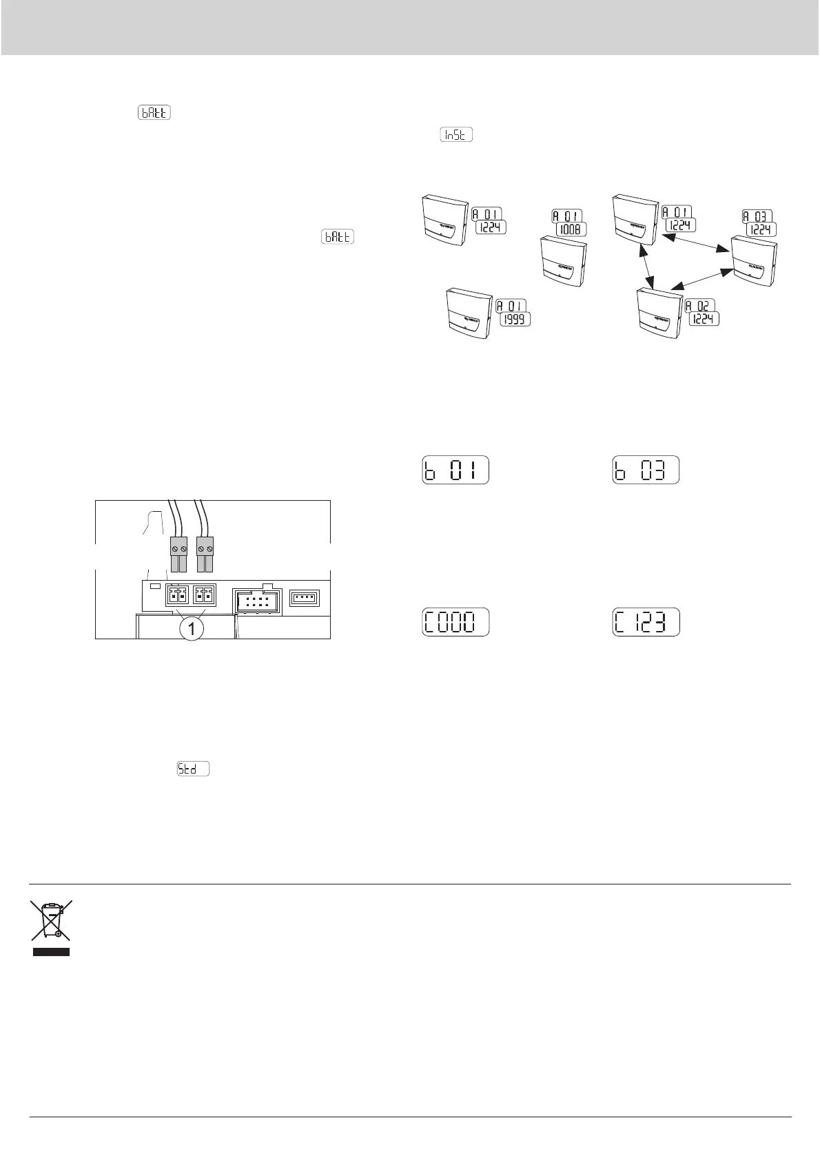
0%XVFRQQHFWLRQ
The M-Bus can be connected temporarily or permanently (installed
SHUPDQHQWO\E\PHDQVRIDFRQQHFWRULQRQHRIWKHWZRSOXJFRQ-
QHFWRUVIRU WKH 0%XVVHUYLFHFRQQHFWRU 7KH FRQQHFWRU LVLQ-
cluded in the scope of supply.
Sealing
2QFHFRPPLVVLRQLQJKDVEHHQFRPSOHWHGWKHQHWZRUNQRGHPXVW
be secured using the seal provided. The seal is inserted into the seal
opening on the right-hand side of the network node.
Network installation
The red MODE key is pressed on a network node Q node 5.5. The key
PXVWEHNHSWSUHVVHGIRUORQJHUWKDQVHFRQGV3UHVVLQJWKLVNH\
changes the network node to installation mode (can be recognised
by
RQ WKH GLVSOD\ DQG WKH ÀDVKLQJ /(' RQ WKHIURQW 7KLV
QHWZRUNQRGHWKHQDXWRPDWLFDOO\FRQ¿JXUHVDOOWKHQHWZRUNQRGHVLQ
installation mode added later into one wireless network.
Three network nodes before in-
stallation:
Display level A alternates be-
WZHHQGLႇHUHQW ZLUHOHVV SULPDU\
addresses and network numbers
(according to the state on deliv-
HU\RIWKH4QRGH
Three network nodes after / dur-
ing network installation:
Display level A permanently
shows wireless primary ad-
dresses and an identical network
number.
Before network installation:
Display level B shows one net-
work node each
After / during network installa-
tion:
Display level B shows the num-
ber of network nodes in the net-
work.
Installation of the metering devices:
The metering devices are set to installation mode.
Before network installation:
Display level C shows no meter-
ing devices in the network.
After / during network installation:
Display level C shows the num-
ber of metering devices in the
network.
Completing installation of the network
)LQDOO\LWPXVWEHHQVXUHGWKDWDOOQHWZRUNQRGHVKDYHVDYHGWKHFRUUHFWQXPEHURIPHWHULQJGHYLFHVDQGQHWZRUNQRGHVOHYHOEDQG&
PXVWEHFKHFNHG7RTXLWLQVWDOODWLRQPRGHWKHUHG02'(NH\RQRQHRIWKHQHWZRUNQRGHVPXVWEHNHSWSUHVVHGIRUWZRVHFRQGV7KH
display for standard mode
ZLOODSSHDU7KHIURQW/('FDQÀDVKIRUXSWRDQRWKHUVHFRQGV7KHQDOOWKHQRGHVLQWKHQHWZRUNDUH
set to standard mode.
M-Bus
)L[HGFRQQHFWLRQ
M-Bus connection for gateway
and service
 Loading...