Installation and Owner’s Manual – Radiant
®
Heat Pump
6
H4121 025960 Rev. B
• Allow 200m
3
of free space
surrounding the unit. This provides
clear ambient airow assisting the
product’s performance.
• The area must also be clear of debris
such as leaves and tree branches.
• Allow 700 mm clearance above and
150mm clearance to either side of
the unit as shown in the Rough-In
Diagram on page 2.
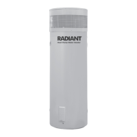
• Ensure there are no obstructions
placed on top of the unit.
• Total clearance required from ground
to install unit is approximately
2410mm.
• Refer to the Rough-In Diagram on
page 2 for detailed information on
position of plumbing.
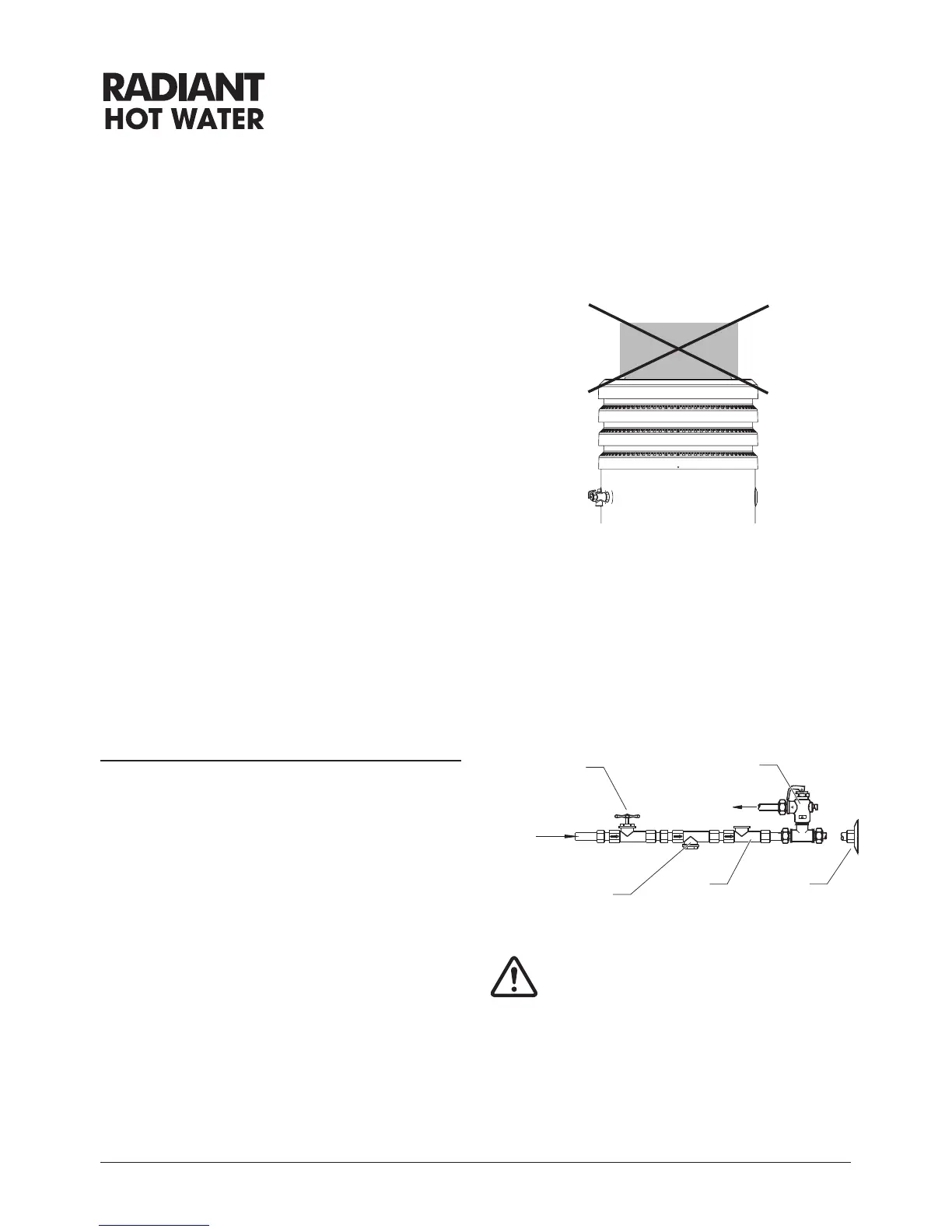
• An approved isolating valve, non-
return valve, line strainer (optional
but recommended), and union must
be tted between the supply main
and the RP¾/20 socket in the water
heater.
• All ttings must be approved by the
relevant installation Authority.
Installation Instructions
Drain
Union
Connection
Non-return
Valve
Line
Strainer
Cold Water
Inlet
control valve
Note: For S.A. and W.A., it
is a state requirement that
a cold water expansion
control valve be tted on
the cold water supply line
between the non-return
valve and the water heater.
 Loading...