.-----+--_
OUTPUT
R
28
270
5.0 VOLTS
T
!
02
SYNC-
- -
-::\
Video
Mixing
The
Video Mixing circuitry generates
the
composite
video signal
for
the
display.
The
video
mixer accepts alphanumeric
or
graphics
dot
data from
the
shift register, level-shifts it, and
places
it
atop
the
composite syncs.
The
compo-
site waveform
is
then
buffered
to
drive a
75
ohm
impedance and
is
sent, via cable,
to
the
Video
Display.
A
23
120
A
27
330
Dot
data from
Shift
Register
Z10
or
Z11
is
applied
to
Z30, pin 3
or
pin 2. You should never
see
both
pin 3 and pin 2 active
at
the
same time.
While
Z10
is
outputting
alphanumeric data, Z11,
pin 13 should be low. Conversely, if Z11
is
out-
putting
graphic data, Z10, pin 13 should be low.
The
net
result
at
pin 1, Z30,
is
a single wave-
shape
of
video
dot
data. This
data
is
applied
to
Z41,
pins6
and 7.
The
composite sync
data
is
sourced from Z5,
pin 8, and
is
applied
to
the
base
of
transistor
02.
Each
time
the
base
of
02
goes
to
about
0.6
volts
below 5 volts, Q2
turns
on, which applies 5 volts
to
resistor R28. (Actually,
the
voltage applied
to
R28 will be less
than
5.0 volts,
due
to
the
satura-
tion
voltage
of
Q2.)
The
dot
data from Z30, pin 1,
is
inverted
by
Z41,
pins 6 and 7.
The
resulting
output
at
pin 5
is
a normally-low signal which goes high only
when
the
Shift
Registers
output
a
dot.
Z41
is
a
high
current
driver. The
output
at
pin 5
is
the
collector
of
the
output
buffer transistors. So,
essentially, we have
the
video and sync going
to
two
transistors. These transistors
act
as switches
controlling
current
flow through resistor net-
work
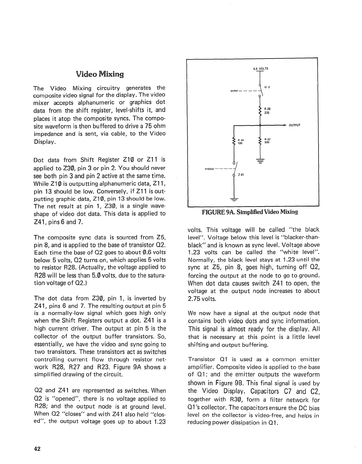
R28, R27 and R23. Figure 9A shows a
simplified drawing
of
the
circuit.
Q2 and Z41 are represented as switches. When
Q2
is
"opened".
there
is
no voltage applied
to
R28;
and
the
output
node
is
at
ground level.
When Q2
"closes"
and
with Z41 also held "clos-
ed",
the
output
voltage goes up
to
about
1.23
42
VIDEO----
241
FIGURE
9A.
Simplified
Video
Mixing
volts. This voltage will be called
"the
black
level". Voltage below this level
is
"blacker-than-
black"
and
is
known
as
sync level. Voltage above
1.23 volts can be called
the
"white
level".
Normally,
the
black level stays
at
1.23 until
the
sync
at
Z5, pin 8, goes high, turning
off
02,
forcing
the
output
at
the
node
to
go
to
ground.
When
dot
data causes switch
Z41
to
open,
the
voltage
at
the
output
node increases
to
about
2.75
volts.
We
now
have a signal
at
the
output
node
that
contains both video
dots
and sync information.
This signal
is
almost ready for
the
display.
All
that
is
necessary
at
this
point
is
a little level
shifting and
output
buffering.
Transistor
01
is
used
as
a
common
emitter
amplifier. Composite video
is
applied
to
the
base
of
Q1; and
the
emitter
outputs
the
waveform
shown
in
Figure
98.
This final signal
is
used
by
the
Video Display. Capacitors C7
and
C2,
together
with R30, form a filter network for
Q1
's collector. The capacitors ensure
the
DC
bias
level on
the
collector
is
video-free,
and
helps
in
reducing
power
dissipation
in
Q1.
 Loading...