8
Installing the Manifold (Continued)
Tip: Partially assembling the manifold ahead of time will make the job easier. Be sure
that the valve is installed horizontally according to the arrows printed on the body for
the direction of flow. Valve operation may be erratic and valve warranty is void if in-
stalled backward or in a vertical position. Call our toll-free Technical Services Hotline
for any questions on system installation: 1-800-RAIN-BIRD.
CAUTION: Do not use plumber's pipe dope on valve threads when installing. Chemi-
cals in the pipe dope may react with the plastic in the valve body causing the valve to
weaken and crack at the threads. Three wraps of Teflon tape should be sufficient to
create a leak-proof seal.
How to Operate
Several models of Rain Bird 24 Volt valves are available for home use. Minimum cur-
rent requirements for opening the smaller valves is .30 amps and for holding the valve
open is .19 amps. Larger valve models have slightly higher requirements. All Rain Bird
valves are designed to work with Rain Bird timers and other timers that have a power
output sufficient to activate the valve. Your Rain Bird valve offers some simple fea-
tures you should be familiar with. Note: Some valves have only part of these features.
See the diagram above and on the previous page for information on flushing the
valves.
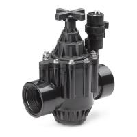
a. Flow control -
Regulates the amount of water passing through the valve. (Not
available on all models.)
b. Manual bleed -
Turns the valve on manually by "bleeding" water off of the di-
aphragm. External bleed models have a knob or screw to turn
and the water sprays out of the top of the valve. Internal bleed
models have a open/close knob or require a
1
/
4
turn of solenoid
and water bleeds off inside the valve.
c. Manual On/Off -
Turn solenoid
1
/
4
turn counterclockwise to turn valve on manu-
ally.
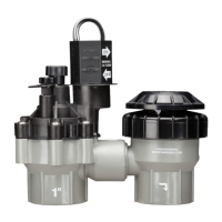
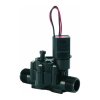
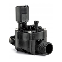
To Flush:
Solenoid
Bleed Knob
(Manual Bleed)
(Manual on/off)
Bonnet
Body
Turn bleed knob 1 full turn counterclockwise and allow water to spray out for 10-15 seconds; turn back
to clockwise position.
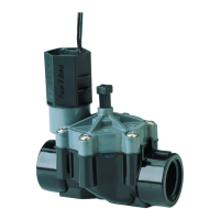
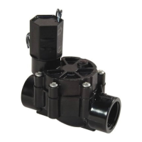
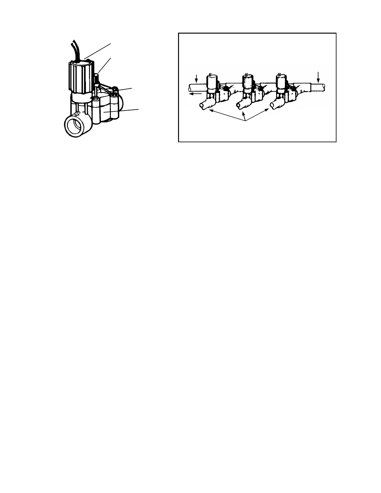
Automatic In-Line
control valves
CP-075 for
3
/
4
” pipe
CP-100 for 1” pipe
Connecting pipe
from water source
PVC Pipe
To other
valves
To Sprinklers
Typical Installation
using PVC pipe
and fittings where no
backflow prevention is
required
 Loading...