Table 1 –
Performance Data
NOZZLE SIZE
(.55") (.63") (.71") (.79") (.87") (.94")
PSI @
14 mm 16 mm 18 mm 20 mm 22 mm 24 mm
Nozzle
Rad. Flow Rad. Flow Rad. Flow Rad. Flow Rad. Flow Rad. Flow
40 103 55 105 72 113 92 131 114 126 134 126 162
50 109 61 111 79 124 101 137 124 136 148 137 177
60 115 66 120 86 133 110 141 136 140 162 142 193
70 121 72 126 93 140 118 146 147 149 175 151 209
80 128 77 128 99 146 127 153 157 161 188 166 224
90 134 82 135 106 151 136 159 168 168 201 175 240
100 140 88 141 113 154 144 164 178 176 214 184 255
(ft.) (gpm) (ft.) (gpm) (ft.) (gpm) (ft.) (gpm) (ft.) (gpm) (ft.) (gpm)
Example (see shaded area):
You have 60 PSI and a 14 mm nozzle; the chart
recommends configuration A or B. This means that your
Rain Gun
®
will operate properly in either configuration,
but the rotation speed will be faster in A than in B.
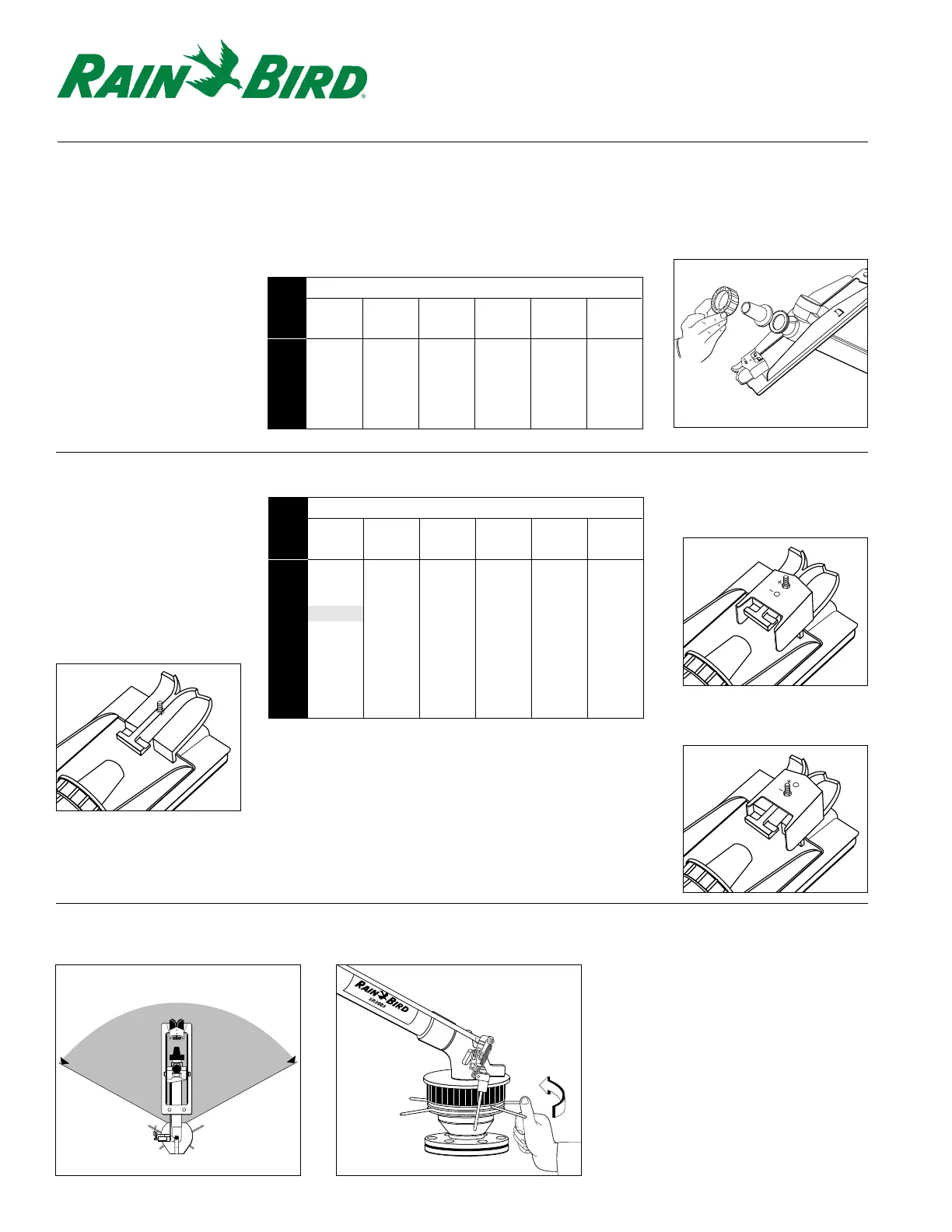
SR3003 / F3002 Configuration Details
Nozzle Selection
Select one of the six nozzles
provided based on your
performance requirements,
available water pressure
(at the Rain Gun), and flow
capacity. Refer to Table 1
and Figure 1.
Spoon Adjustment
Bracket
Install the Spoon
Adjustment Bracket, if
needed, in accordance with
Table 2. Refer to Figures A,
B, and C.
Rotation Angle Adjustment
For part circle (SR3003) model only, adjust desired rotation angle manually as shown.
Figure 1
Table 2 –
Spoon Adjustment Bracket
NOZZLE SIZE
(.55") (.63") (.71") (.79") (.87") (.94")
PRESSURE
14 mm 16 mm 18 mm 20 mm 22 mm 24 mm
PSI
40 A A A A / B A / B A / B
45 A A / B A / B A / B A / B A / B
50 A / B B B B B B
60 A / B B B B B B
65 B B B B B / C B / C
75 B B B B / C B / C B / C
80 B B B / C C C C
90 B B B / C C C C
95 B B / C B / C C C C
100 B B / C B / C C C C
Figure A: Bracket not installed
Provides maximum drive and
rotation speed at low pressures.
Figure 2 Figure 3
Figure B: Plus position (+)
Provides an intermediate
position to regulate rotation
speed at intermediate pressures.
Figure C: Minus position (–)
Provides greatest slowing of
rotation speed at high pressures.