www.raisecom.com User Manual
3
Chapter 3 Device Appearance And Description
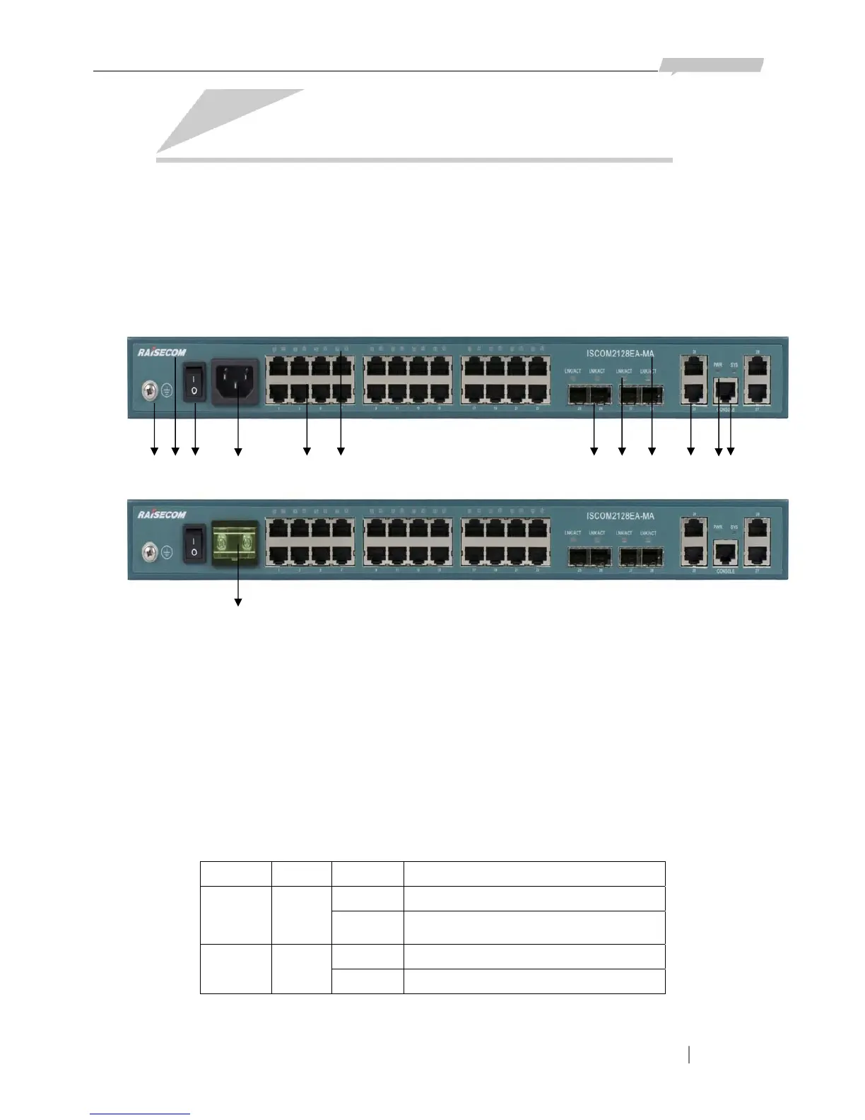
3.1 Front panel and explanation
On the front panel of ISCOM2128EA-MA, there are 24 10/100M Ethernet electrical ports, 4
COMBO ports (4 100/1000M SFP optical ports and 4 100/1000M Ethernet electrical ports), 1
Console port, status indicator LEDs and power supply interface. AC and DC power supply are of
different interfaces, see in the following figures:
1 2 3 4 5 6 7 8 9 10 11 12
13
Explanation:
Number 1 is the Grounding bolt
Number 2 is the logo: RAISECOM
Number 3 is the Power supply switch
Number 4 is receptacle for 220V AC power and number 13 is for DC power
Number 5 is the 24 10/100 Ethernet electrical ports, being numbered as 1-24
Number 6 is the LNK/ACT status indicators for Ethernet electrical ports
Number 7 is the 4 100/1000M SFP optical ports, being numbered as 25-28
Number 8 is the LNK/ACT status indicators for SFP optical ports
Number 9 is model of the switch: ISCOM 2128EA-MA
Number 10 is the 4 100/1000M electrical ports, being numbered as 25-28
Number 11 is the 2 status indicators of switch: SYS and PWR (refer to the panel)
Indicator Color Status Indication
SYS Green
Flickering System works normally
ON/OFF
System is initializing or Software fault at
the very beginning of power on device.
PWR Green
ON System powered on
OFF System powered off
Number 12 is CONSOLE port