Do you have a question about the Raisecom ISCOM2128EA-MA and is the answer not in the manual?
Details specific warranty terms applicable to Raisecom products and replacement parts.
Outlines copyright, reproduction, and translation restrictions for the document.
States copyright ownership and lists registered trademarks of Raisecom and other companies.
Provides contact methods for technical assistance with Raisecom products and solutions.
Offers the URL to access current Raisecom product information online.
Guides users on submitting comments and questions about the ISCOM2128EA-MA device.
Specifies the applicability of the manual to ISCOM2128EA-MA switch versions.
Identifies the intended readers for this user manual, including technical staff.
Lists other relevant manuals for ISCOM2128EA-MA commands and configuration.
Outlines the content and structure of each chapter in the manual.
Explains symbols indicating potential safety hazards during product operation or maintenance.
Provides essential safety practices for handling devices with power connected.
Guidelines for safely connecting the device to AC power sources, following local codes.
Procedures for safely connecting the device to DC power, avoiding short-circuits and fire hazards.
Advises on using ESD-preventive measures to avoid component damage during handling.
Describes the manual's content, installation methods, and cable specifications.
Defines technical terms and acronyms used in the manual for clarity.
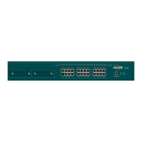
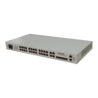
Details the ISCOM2128EA-MA as a professional layer-2 Ethernet switch.
Provides the physical dimensions and weight of the ISCOM2128EA-MA.
Specifies recommended temperature, storage, and humidity ranges for operation.
Details the components and status indicators on the front panel of the device.
Describes the rear panel of the ISCOM2128EA-MA and its features.
Lists the available models of the ISCOM2128EA-MA switch.
Covers installation environment, rack mounting, and grounding procedures.
Details connecting the switch's console port to a PC for configuration.
Provides detailed signaling and pinout information for the console port.
Guides on connecting the switch's Ethernet ports to network devices.
Instructions for connecting the switch to AC or DC power sources.
Provides wiring diagrams for straight-through and crossover network cables.
Explains connecting the switch to power and interpreting status indicators.
Advises on proper installation, environmental conditions, and handling to ensure safety.
| Ports | 24 x 10/100/1000BASE-T, 4 x 1000BASE-X SFP |
|---|---|
| Switching Capacity | 56 Gbps |
| Forwarding Rate | 41.7 Mpps |
| MAC Address Table Size | 8K |
| VLAN Support | 4K VLANs |
| Power Supply | AC 100-240V, 50/60Hz |
| Operating Temperature | 0°C to 50°C |
| Storage Temperature | -40°C to 70°C |
| Operating Humidity | 10% to 90% non-condensing |
| Weight | 3.5 kg |
| Device Type | Switch |
| Jumbo Frame Support | 9K Bytes |
| Dimensions (W x D x H) | 440 x 440 x 44 mm |
| Dimensions | 440 x 440 x 44 mm |
| Layer | L2 |


