www.raisecom.com User Manual
5
Chapter 3 Device Appearance
3.1 Device front panel description
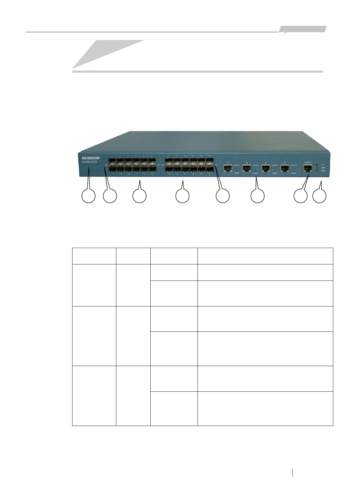
20 SFP interfaces, 4 combo interfaces, 1 CONSOLE interface and dozens of status indicators are
placed on the front panel of ISCOM2924GF switch (see the figure below).
In the figure shown above:
① The logo and model of the switch are RAISECOM and ISCOM2924GF respectively.
② 3 device status indicators: SYS, PWR1 and PWR2.
Indicator Color Status Description
Flickering The system is operating in order. SYS Green
Other
Status
Software fault or the system is initializing
after electrifying.
ON The power supply module on the left is
electrified.
PWR1 Green
OFF The power supply module on the left is not
electrified, or fault occurs on the power
supply.
ON The power supply module on the right is
electrified.
PWR2 Green
OFF The power supply module on the right is not
electrified, or fault occurs on the power
supply.
③ 24 Ethernet interfaces numbered 1 ~ 24. (20 ~ 24 are combo interfaces including both SFP and
RJ-45 interfaces).
④ 24 groups of indicators for the 24 SFP Ethernet interfaces (including 20 independent SFP and the
4 SFP in the combo interfaces). There are 2 indicators of each SFP interface: LNK and ACT.
1 3 24 5 63 4