www.raisecom.com User Manual
8
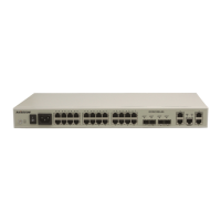
Chapter 4 Installation and Application
4.1 Device model
The device models currently provided are:
Product Model Description
ISCOM2924GF-AC/S Single AC power supply
ISCOM2924GF-DC/S Single DC power supply
ISCOM2924GF-AC/D Double AC power supply
ISCOM2924GF-DC/D Double DC power supply
4.2 Device installation
4.2.1 Environment requirement
There are heat exhaust outlets on both sides of ISCOM2924GF switch. Please leave space on both
sides of the switch to keep air flow unblocked. Please make sure the outlets are not blocked.
4.2.2 Install the device on to a rack
To set the switch firmly into a rack, please fix the installation tray to the switch using the eleven
screws come with the device and fasten the installation handle on to the rack.
4.2.3 Grounding
To ensure the safety of the device and the operator, please make sure that the grounding terminal is
well connected to the earth.
4.3 The connection of the switch
4.3.1 Connect to console
ISCOM2924GF switch provides a RS-232 interface in the form of RJ-45 as the CONSOLE interface.
After connecting the CONSOLE interface of ISCOM2924GF switch to the serial port on the PC
using the provided cable, users can configure and manage the switch through PC.
1) CONSOLE interface signal definitions of the switch
The CONSOLE interface of ISCOM2924GF is in the form of RJ-45. The RJ-45 connector and jack
and the corresponding pin number is shown in the figure below.