12
Proceed as follows:
• Remove all output tubes and turn the preamp volume control all the way down.
• Turn the amp on and leave it on.
• While monitoring the current, put a pair of tubes into sockets Number One and Number Two.
Allow one minute on the clock for the two tubes to warm up.
• If the current comes up to about half the normal amount, both those tubes are good.
• Remove those tubes and install another pair, also in sockets one and two. Continue on until a
fuse blows, or the tubes won’t bias up.
• Then buy or borrow a known good tube (remember, if it is actually bad, we’ll pay for the replace-
ment), and using it as a mate, use the process of elimination to figure out which of the tubes is
bad by substituting the good tube. At this point, if you get lucky, only one trial will be needed. If
you are not lucky, then it will take two trials.
• Now you can turn the amp off.
You will be able to install and remove the tubes with your bare fingers if you do it within
about a minute or so of installing each fresh set. That’s because it takes substantially longer than
a minute for the tubes to get too hot to hold.
Matching Output Tubes
Matching output tubes is not necessary, thanks to the DC restorer.
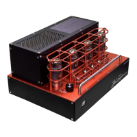
New Amplifier Smell
Like a brand new car, this amplifier possesses a “new amplifier smell,” even though it has
been built from new parts. When powered up for the first time, the fresh paint and recent oils on
the tubes will create a new, hot amp smell. I find it sort of pleasant, but you may not. It will dissi-
pate with use, usually requiring about two weeks of normal operation.
Circuit Description
The input stage consists of a 12AX7 current sourced long-tailed class A amplifier, which is
direct coupled to a long-tailed balanced pair comprised of a 12AT7. The 12AT7 drives the grids of
the KT 120 output tubes through a pair of coupling capacitors that provide low frequency loop-gain
stability. A vacuum tube diode DC restorer ensures that the bias voltage remains correct over the
entire audio signal cycle.
The output tubes are arranged in push-pull parallel, four in all. The screen grids are operat-
ed at approximately 340 Volts provided by a separate power supply formed by one- half of a volt-
age doubler supplying the plates with 685 Volts.
The power supply consists of a large power transformer, with energy storage that is far
greater than necessary. AC filament voltage is biased to approximately 60 volts. Multiple decou-
pling filter sections are used with load regulation obtained through constant current loading.
Bias voltage adjustment by a bias control, and bias current is measured by a meter that
simultaneously senses current for all four output tubes. A tube fuse is mounted on the rear apron
and provides protection for the output section in the event of a catastrophic vacuum tube failure.