Do you have a question about the RAM S Series and is the answer not in the manual?
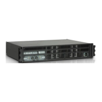
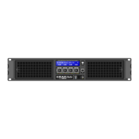
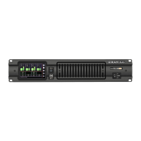
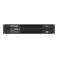
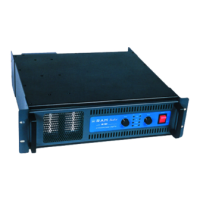
Overview of the S Series power amplifiers, their purpose, and unique features.
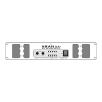
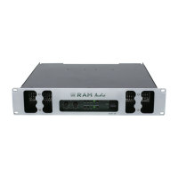
Details unique features like compact design, laser-cut front panels, Neutrik connectors, and protection systems.
Identifies and explains front panel controls like level knobs, LEDs (SIGNAL, TEMP, PMS, ICL), and the power switch.
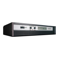
Describes rear panel connectors (XLR, Speakon) and switches (Link/Dual, Gain, Configuration).
Explains how to wire XLR connectors for balanced and unbalanced input signals, including important polarity notes.
Details setup for operating the amplifier in stereo mode, connecting inputs and speakers for independent channels.
Describes how to link input signals between adjacent channels for easier setup in stereo configurations.
Explains how to configure the amplifier for bridge mode, connecting a single output to a speaker for increased power.
Details how to use rear panel mini-dips to set configurations like subsonic filter, ICL, and bridge mode.
Explains how to interpret front panel LEDs (SGNL, TEMP, PMS, ICL) to diagnose common operational problems.
Explains the PMS system's role in monitoring and controlling current to prevent damage under various conditions.
Details the ICL system's function to prevent speaker damage from clipping while maintaining audio quality.
Describes the SSPT protection against incorrect loads or short circuits to prevent output transistor failure.
| Signal to Noise Ratio | >100dB |
|---|---|
| Frequency Response | 20Hz-20kHz |
| Input Impedance | 20k Ohm |
| Connectors Input | XLR, TRS |
| Connectors Output | Binding Posts |