Lokalisierung der
Funktionen
See Figure
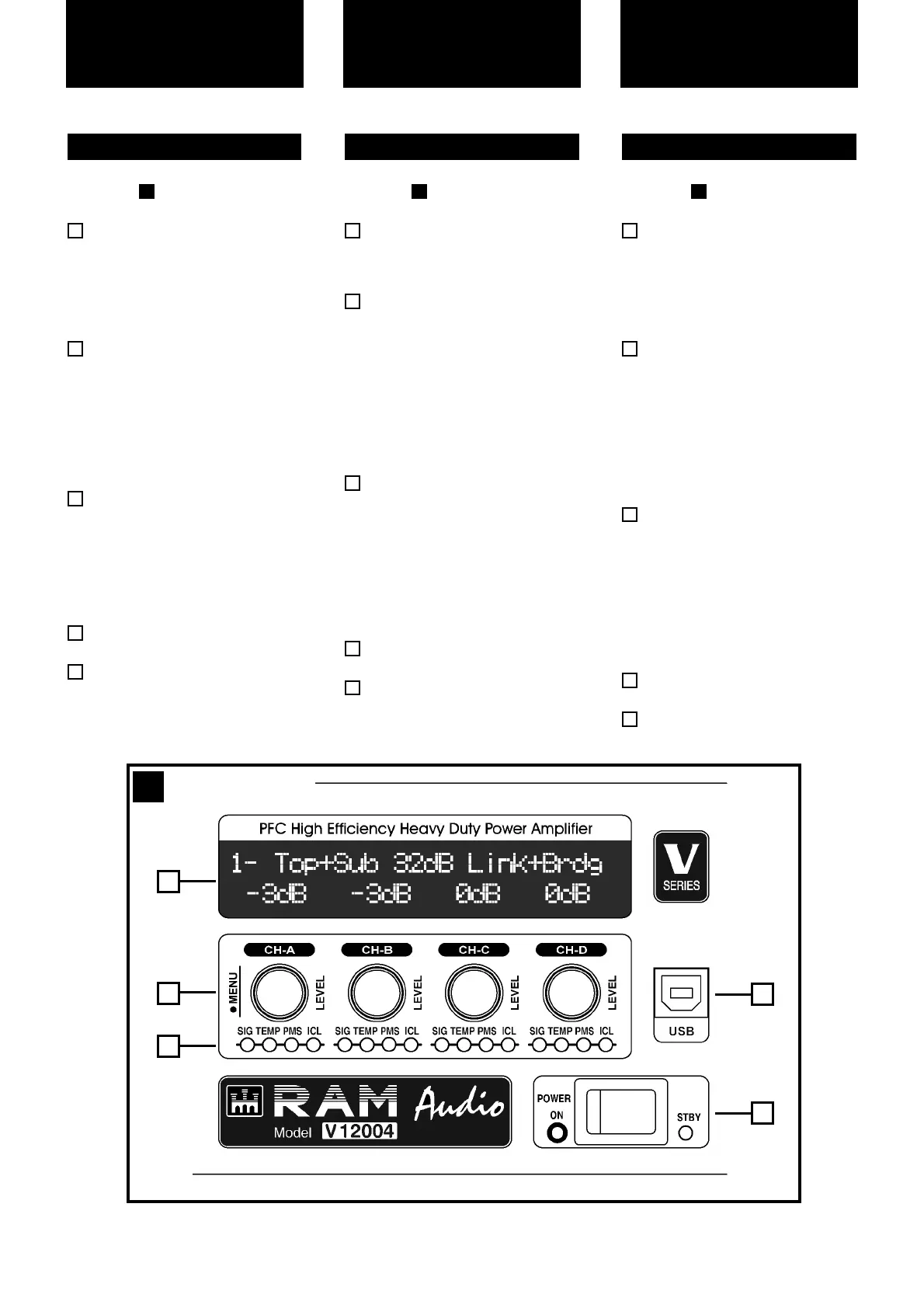
Configuration and signal attenua-
tion level control knobs: Permit
independent control of each chan-
nel’s attenuation and change the
amplifier configuration. See page
10.
SIGNAL: This LED indicates pres-
ence of signal at the inputs.
TEMP: This LED shows tempera-
ture protection is active.
PMS: LED indicating PMS in opera-
tion (see page 13)
ICL: LED indicating Intelligent Clip
Limiter in operation (see page 13).
Main Power Switch:
Position I: Connects the amplifier's
current feed. (Blue LED on).
Position O disconnects the Power.
Position II (optional): Stand-by
Mode. The Amp's Power is activated
remotely via Ethernet. (Amber LED).
Display: See page 10.
USB Connector for firmware
upgrade and optional DSP control.
5
4
3
2
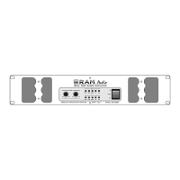
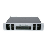
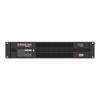
2.1 Front Panel
1
1
Siehe Fig.
Lautstärkeregler: diese ermögli-
chen die Signalstärke am Ausgang.
siehe Seite 10.
SIGNAL: Wachanzeige des einge-
henden Signals.
TEMP: LED-Anzeige leuchtet wenn
der Schutz vor Überwärmung ein-
geschaltet ist.
PMS: Die LED zeigt an, dass das
PMS in Betrieb ist (siehe Seite 13)
ICL: Die LED zeigt an, dass der
Intelligent Cliplimiter arbeitet (siehe
Seite 13).
Beleuchteter Hauptstromschalter:
Position I: Schaltet die Endstufe ein.
(Blaue LED leuchtet).
Position O Schaltet die Endstufe
aus.
Position II (optional): Stand-by
Modus. Die Endstufe kann über
Ethernet eingeschaltet werden.
(Gelbe LED).
Display: siehe Seite 10.
USB Connector for firmware upgra-
de and optional DSP control.
5
4
3
2
2.1 Frontplatte
1
1
Controls:
Where and What?
Ver Figura
Configuración y atenuadores de
control de nivel: permite modificar
el nivel de la señal de entrada inde-
pendientemente para cada canal y
cambiar la configuración del amplifi-
cador.Ver página 10.
SIGNAL: LED indicador de presen-
cia de señal en la entrada.
TEMP: LED indicador de actuacion
de las protecciones por sobrecalen-
tamiento del amplificador.
PMS: indica que esta actuando el
sistema PMS (Pág. 13).
ICL: indica que esta funcionando el
sistema anticlip ICL (Pág. 13).
Interruptor principal:
Posición I: conecta la alimentación
de corriente (LED azul)
Posición O: desconecta la alimenta-
ción de corriente.
Posición II (opcional): Modo Stand-
by. El amplificador está activado
remotamente vía Ethernet (LED
ambar)
Pantalla: ver página 10.
Conector USB para la actualización
del firmware y control del DSP.
5
4
2.1 Panel frontal
1
1
2
3
Ubicación y función
de los Controles
4
1
Front Panel
1
4
2
3
5