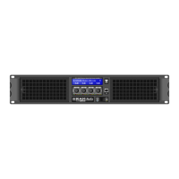
Installation and
Operation
Instalación y
operación
The amplifier can operate on three dif-
ferent configurations: DUAL, LINK or
BRIDGE. The connections for the three
modes are different.
See Figure
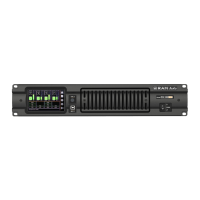
- Set the Amplifier Mode to “DUAL”.
- Select the chosen Gain (Default set-
ting 32dB).
- Connect the signal lines to the female
XLR connectors on all channels.
- Connect the speakers’ lines to the cor-
responding Speakon on the amp
respecting the polarity.
- Use the level control knob on the front
panel to adjust each channel indepen-
dently.
- Each signalling LED group will show
its corresponding channel status.
See Figure
- Operate as Dual Channel Mode with
the signal input linked to another adja-
cent channel.
See Figure
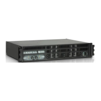
- Set the configuration mode to
“BRIDGE” (see page 9).
- Select the chosen Gain (Default set-
ting 32dB).
- Connect a signal line to input female
XLR Channel “A” (or Ch-C in 4 chan-
nel models).
- Connect the speaker line to the
Channel A Speakon (or Ch-C in 4
channel models) wired to +1 and -2. In
this way pin +1 is positive.
- Use Channel-A (or Ch-C in 4 channel
modes) control knob to adjust the
amp’s output.
- The signalling LED groups will show
the single channel status.
WARNING! The “
-
“ pins, do not
have to be Ground!
4
3.1.2 LINK Channel Mode
3
3.1.1 DUAL Channel Mode
5
3.1.3 BRIDGE Channel Mode
Existen tres modos de funcionamiento
posibles del amplificador: Dual, Link, o
Puente. Las conexiones en cada caso
son diferentes.
Ver figura
- Coloque el commutador del panel tra-
sero en la posicion Dual.
- Seleccione la ganancia elegida (32dB
por defecto)
- Conecte las señales de entrada de
todos los canales por sus respectivos
XLR hembra.
- Conecte los altavoces a los Speakon
de cada canal, respetando polaridad.
- Utilice el control de nivel de cada
canal para controlar independiente-
mente los niveles de salida
- Los LEDs de señalizacion indicaran la
situacion independientemente de cada
canal.
Ver figura
- Funcionar como modo Dual con la
señal de entrada linkada a otro canal
adyacente.
Ver figura
- Coloque los commutadores del panel
trasero en la posicion Bridge (pág. 9).
- Seleccione la ganancia elegida (32dB
por defecto)
- Conecte la señal de entrada al amplifi-
cador por el conector de entrada XLR
hembra del Canal A (o canal C en una
etapa de 4 canales).
- Conecte la línea de altavoces al
Speakon del canal A (o el C en un
modelo 4 canales) cableando al +1 y
el -2. De esta forma el pin +1 es posi-
tivo.
- Utilice el control de nivel del canal A (o
C en modelo de 4 canales) para con-
trolar el nivel de salida del amplifica-
dor.
- Los LEDs de señalizacion de cada
canal indicaran indistintamente la
situacion del unico canal de salida.
¡ATENCIÓN! ¡Los pins “-” no tienen
que ser tierra!
3.1.1 Modo Dual (Stereo)
3
3.1.2 Modo LINK
4
3.1.3 Modo Puente (Bridge)
5
Es gibt drei Funktionsmöglichkeiten die-
ser Endstufe: Dual, Link und Bridge. Die
Anschlüsse sind in den drei Fällen
unterschiedlich.
Siehe Fig.
- Stellen Sie den Modusschalter auf die
Modus “Dual”.
- Bitte wählen Sie den
Eingangspegelwert (Werkseinstellung
32 dB).
- Schließen Sie alle Eingangssignale an
ihre entsprechenden XLR-Buchsen.
- Schließen Sie die Lautsprecher an die
entsprechenden Speakon an, bitte die
Polarität ist beachten.
- Benutzen Sie die Lautstärkeregelung
der entsprechenden Kanäle um den
gewünschten Lautstärkepegel zu errei-
chen.
- Die LED-Anzeigen geben den Status
der beiden Kanäle an.
Siehe Fig.
- Gehen Sie wie im Dual-Channel-
Modus vor, wobei das Eingangssignal
mit einem angrenzenden Kanal ver-
bunden ist.
Siehe Fig.
- Setzen Sie den Konfigurationsschalter
auf die Modus “BRIDGE” (Siehe Seite
9).
- Wählen Sie den Einganspegelwert auf
dem Schalter (Werkseinstellung 32
dB).
- Schließen Sie das Eingangssignal an
die XLR-Buchse “A” an (oder Kanal C
bei 4-Kanalmodellen).
- Schließen Sie den Lautsprecher an
den Kanal “A” Speakon (oder Kanal C
bei 4-Kanalmodellen) verkabelt mit +1
und -2 (+1 ist positiv).
- Benutzen Sie Kanal A (oder Kanal C
bei 4-Kanalmodellen) Potentiometer
für die Regulierung des Endstufenaus-
ganges.
- Die LED-Anzeigen werden den Status
des Ausgangkanals angeben.
ACHTUNG! The “
-
“ pins, do not
have to be Ground!
4
3.1.2 LINK Kanalmodus
3
3.1.1 DUAL Kanalmodus
5
3.1.3 Bridge Kanalmodus
7
Anschluss und
Inbetriebnahme
 Loading...