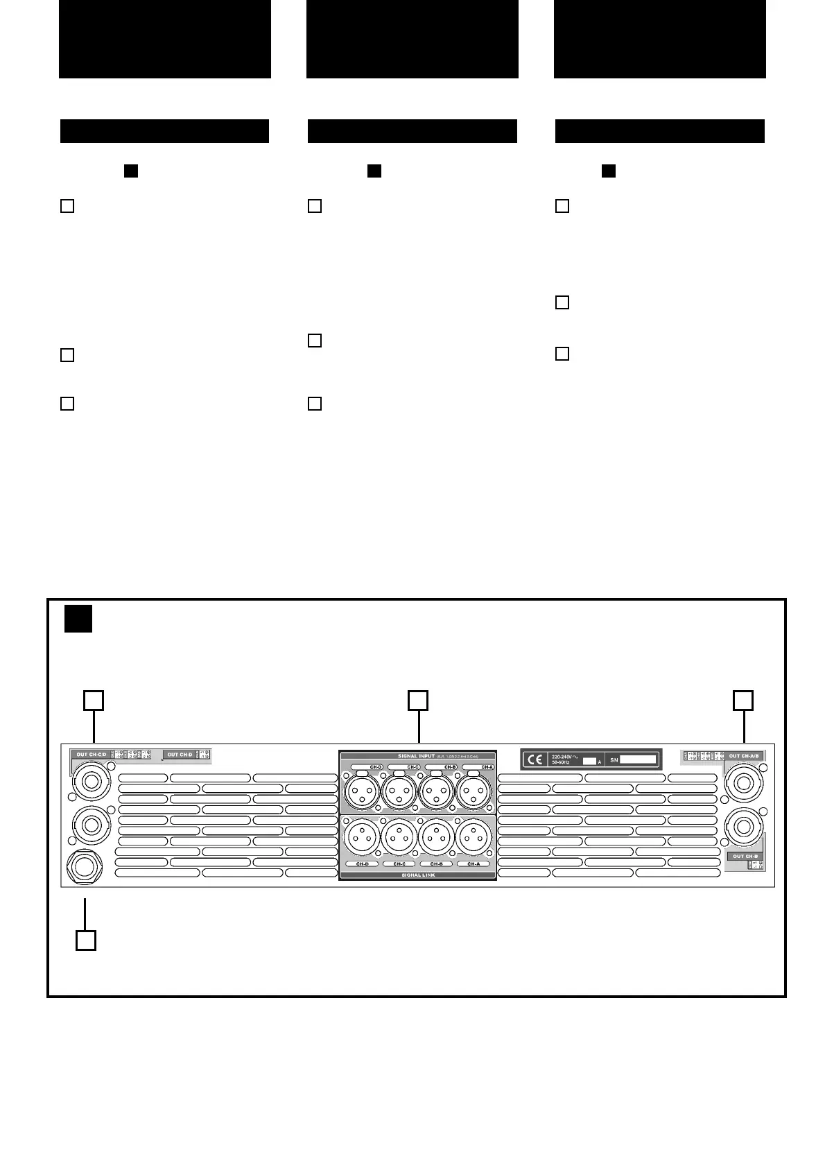
See Figure
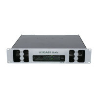
Signal Input: Female Neutrik
®
XLR
Connectors for the amplifier’s signal
input.
Signal Link: Male Neutrik
®
XLR
Connectors for daisy chaining input
signal to other amplifiers (parallel
connected to female input connec-
tors).
Speaker connectors: Neutrik
®
Speakon to connect the speakers.
Mains Power Cord: to connect the
amplifier to the mains network. The
colour code is:
Blue: Neutral
Brown: Live, single phase
Yellow-green: Protective Earth
3
2
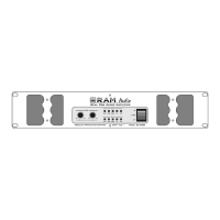
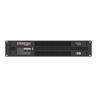
2.2 Rear Panel
1
2
Siehe Fig.
Eingangssignal: Neutrik
®
-XLR
Buchsen für den Signaleingang der
Endstufe.
Signallink: Parallele XLR-Ausgänge
zur Zusammenschaltung der
Eingangssignale mehrerer
Endstufen.
Lautsprecheranschluss: Neutrik
Speakonstecker zum Anschluss an
Lautsprecher.
Mains Power Cord: to connect the
amplifier to the mains network. The
color code is:
Blue: Neutral
Brown: Live, single phase
Yellow-green: Protective Earth
3
2.2 Rückplatte
2
1
2
Lokalisierung der
Funktionen
5
Controls:
Where and What?
Ver Fig.
Entrada de señal: conectores hem-
bra Neutrik
® XLR de señal de
entrada del amplificador.
Señal-Link : conectores macho
Neutrik
® XLR para linkar la señal
de entrada a otros amplificadores.
Conectores para los altavoces:
Speakon Neutrik
® para conectar los
altavoces.
Cable de red: para conectar el
amplificador a una red eléctrica. El
código de color es:
Azul: neutro.
Marrón: Vivo, fase simple.
Amarillo-verde: protección a tierra.
2.2 Panel Trasero
2
1
2
3
Ubicación y función
de los Controles
2
Rear Panel
22
1
3