6 7
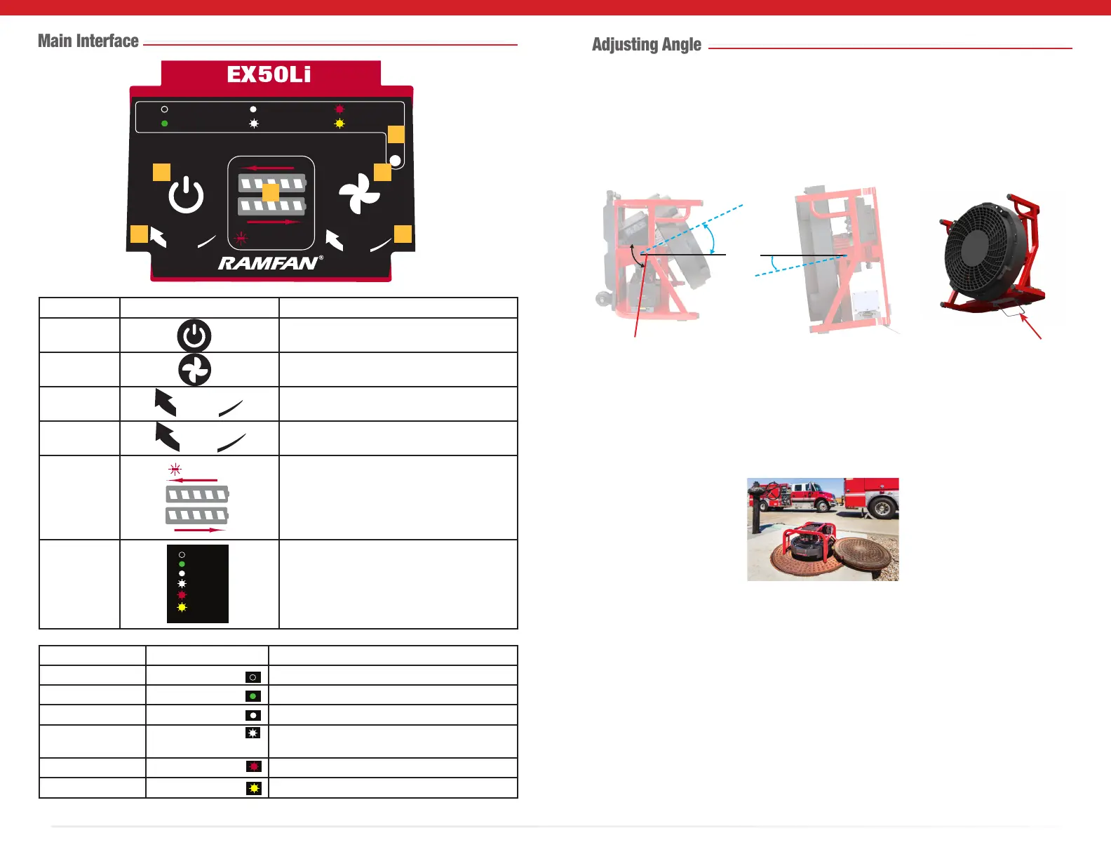
Number Symbol Indicate Function
1 WakeButton/EmergencyStopButton
PressandholdWAKEbuttontostart.
2 MaximumSpeed(DC)Button
PressMAXbuttonfor2seconds.
3 LEDSceneLightsknob
On,o,onhighoronlow.
4 SpeedControlknob
Controlledoperationfrom0tofullspeed
5
BatterystatusLEDlights
strobeduringcharge;remainsonfor5min
whenchargingiscomplete.
R
VentilatorStatusLEDLights
Seetablebelowfordetails.
L
BAT. FAULT
AC PWR
DC PWR
MAX
FAULT
NO PWR
STORAGE
MODE
Color Status Description
O NOPWR Poweriso
Green (Solid) ACPWR VentilatorisconnectedonACPowerSupply
White (Solid) DCPWR VentilatorisrunningonDCPowerSupply
White (Flashing) MAX VentilatorisrunningonMaximumspeed-DC
PowerSupply
Red (Flashing) FAULT Faultontheventilator
Yellow (Flashing) STORAGEMODE Storage/TransportMode
L
R
BAT. FAULT
PUSH FOR
WAKE | STOP
PUSH FOR
MAX
AC PWR
DC PWR FAULT
NO PWR
STORAGE
MODE
MAX
Intellisense
TM
E3
LIGHTS
SPEED
1
2
3 4
5
6
AC PWR
DC PWR
MAX
FAULT
NO PWR
STORAGE
MODE
AC PWR
DC PWR
MAX
FAULT
NO PWR
STORAGE
MODE
AC PWR
DC PWR
MAX
FAULT
NO PWR
STORAGE
MODE
AC PWR
DC PWR
MAX
FAULT
NO PWR
STORAGE
MODE
AC PWR
DC PWR
MAX
FAULT
NO PWR
STORAGE
MODE
AC PWR
DC PWR
MAX
FAULT
NO PWR
STORAGE
MODE
Performthisproceduretoadjustthepositionoftheventilator.Useyourhand
tounscrewthetiltadjustmentknob,andthenlockitinplacefromabove,andheldinthe
inclinedpositionbytighteningtheknob.Fornegativetilt,usethenegativetiltbracket.This
providestiltup/downadjustment,from-10to+34degrees.
Forconnedspacerescueoperations,youcanplacetheventilatordirectlyontopofa
manhole.Tiltrangefrom-90to+90degrees.Notethatthosepositionscandirectairow
downwardorupward
Negative tilt bracket
(Accessory)
-10
o
34
o
Loosen
Tighten
Tilt adjustment knob