– 18 –
<For examples>
In case of Fig. 5-2, defective IC501 or defective
connection between IC501 and IC518.
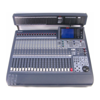
5.7. DSP Meter Signal Test (METER SIGNAL
TEST)
8
Move the Cursor to most bottom position by either UP or
DOWN Cursor Key.
8
Select the Diagnostic Item (DIAG3) by either LEFT or
RIGHT Cursor Key.
8
Press the Enter Key, the Diagnostic Menu 3 as shown in
Fig. 5-3 is displayed.
Fig. 5-3
8
Select the METER SIGNAL TEST Item by either UP or
DOWN Cursor.
8
Execute the METER SIGNAL TEST Item by pressing the
Enter Key.
8
When executing, the Self Check will start for the Meter
Signal Paths from the nineteen DSP ICs (IC501 - IC519)
to Multi IC (IC526).
8
A result after Self Check, displayed "OK" in passed item
and displayed "NG" in defective item.
5.8. DSP D-RAM Test (D-RAM TEST)
8
Referring to Fig. 5-3, select the D-RAM TEST Item by
either UP or DOWN Cursor.
8
Execute the D-RAM TEST Item by pressing the Enter Key.
8
When executing, the Self Check will start for the D-RAMs
(IC528 - IC532) Signal Paths from four DSP ICs (IC505 -
IC508) to Multi IC (IC526).
8
A result after Self Check, displayed "OK" in passed item
and displayed "NG" in defective item.
DIAG1
DIAG3
DIAGNOSTICS
T.C.
SCENE
SEL CH
xxx
IC NO
METER SIGNAL TEST
D–RAM TEST
OK
502
OK
501
OK
503
OK
04
OK
505
OK
507
OK
506
OK
508
OK
509
OK
510
OK
512
OK
511
OK
513
OK
514
OK
515
OK
517
OK
516
OK
518
OK
519
DIAG2 DIAG4 DIAG5 DIAG6 EXITDIAG3
OK
528505
OK
529506
OK
531507
OK
532508
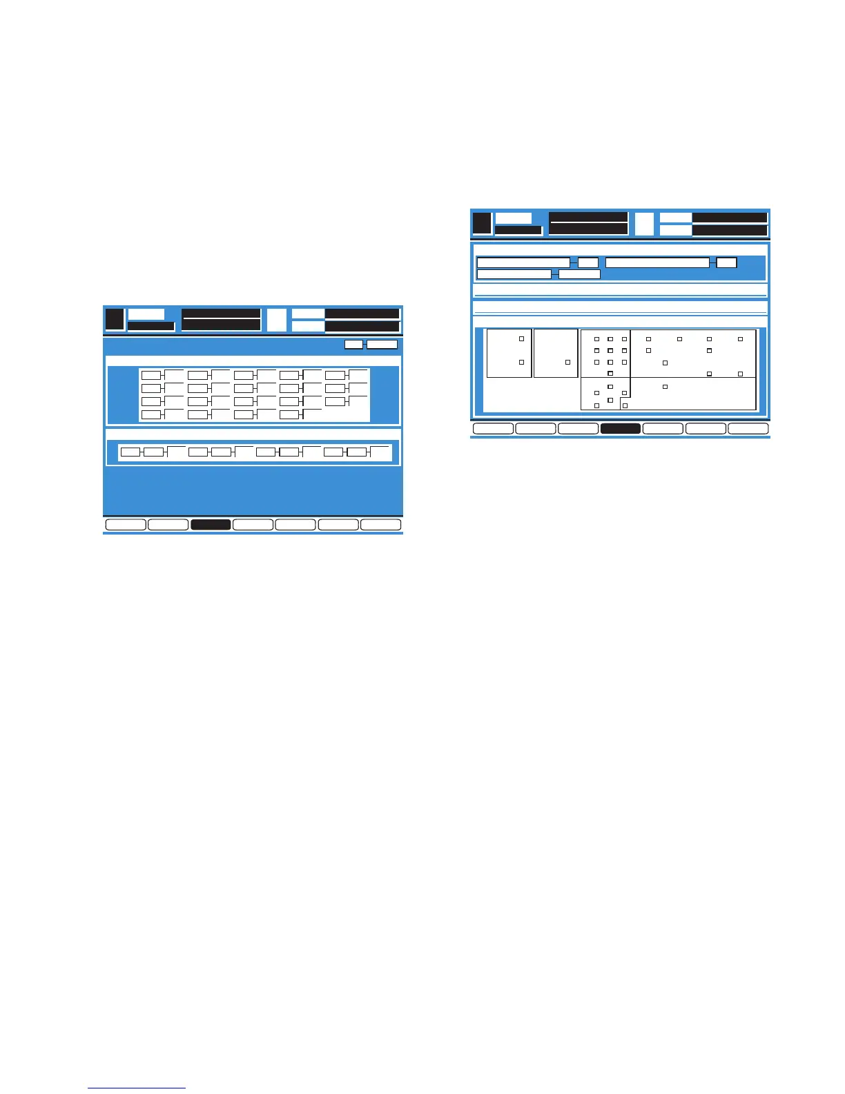
5.9. Digital Interface Test (DIGITAL I/F TEST)
8
Move the Cursor to most bottom position by either UP or
DOWN Cursor Key.
8
Select the Diagnostic Item (DIAG4) by either LEFT or
RIGHT Cursor Key.
8
Press the Enter Key, the Diagnostic Menu 4 as shown in
Fig. 5-4 is displayed.
Fig. 5-4
8
Connect the Record Output Connector and 2TR A Input
Connector, connect the AUX SND1/2 Connector and AUX
RTN1/2 Connector.
8
Select the DIGITAL I/F TEST Item by either UP or DOWN
Cursor.
8
Execute the DIGITAL I/F TEST Item by pressing the Enter
Key.
8
When executing, the Self Check will start for the signal
paths Record Output Connector to 2TR Input Connector
and AUX SND1/2 Connector to AUX RTN1/2 Connector.
8
A result after Self Check, displayed "OK" in passed item
and displayed "NG" in defective item.
5.10.Word Clock Indication (WORD CLOCK)
8
Referring to Fig. 5-4, a presence Master Word Clock
Frequency and Lock/Unlock Status will be displayed.
8
Displayed always without any Item Selection and
Execution.
5.11. LED Test (LED TEST)
8
Referring to Fig. 5-4, select the LED TEST Item by either
UP or DOWN Cursor.
8
Execute the LED TEST Item by pressing the Enter Key.
8
When executing, all LEDs except Switch LEDs lit.
8
Press Enter Key to finish the LED Test.
DIAG4
DIAGNOSTICS
LED TEST
T.C.
SCENE
DIGITAL I/F TEST
SEL CH
SW&LED TEST
SW TEST
DIAG4 DIAG5 DIAG6 EXITDIAG2 DIAG3DIAG1
OKOKREC OUT
B
2TR IN AUX SEND
B
AUX RTN
44.1 KHZWORD CLOCK IN
METER UTILITY MIDI D-I/O
AUTOMATION
SOLO
STORE RECALL
GROUP
UNDO
MMC/CURSOR
CURSOR MODESTOP
123
456
78
0
PLAY
REW FF
9
CHANNEL
ENTER
PARAMETER
SELECT