– 19 –
5.12. Switch LED Test (SW&LED TEST)
8
Referring to Fig. 5-4, select the SW&LED TEST Item by
either UP or DOWN Cursor.
8
Execute the SW&LED TEST Item by pressing the Enter
Key.
8
When executing, all Switch LEDs become blinking
sequentially.
8
When press the Switch which blinking LED, this LED
becomes lit and next LED becomes blinking.
When press the Enter Key instead of the Blinking LED
Key, this LED becomes off and next LED becomes
blinking (Skip Function).
8
The Self Check of the Switch LED Test is finished after
checked all of the Switch LEDs.
5.13. Switch Test (SW TEST)
8
Referring to Fig. 5-4, select the SW TEST Item by either
UP or DOWN Cursor.
8
Execute the SW TEST Item by pressing the Enter Key.
8
When executing, all Switches become reverse indication
sequentially.
8
When press the reverse indication Switch, next Switch
position becomes reverse indication.
When press the Enter Key instead of the reverse
indication Switch, this reverse indication Switch will be
released reverse indication and next Switch position
becomes reverse indication (Skip Function).
8
The Self Check of the Switch Test is finished after
checked all of the Switch LEDs.
5.14. Knob Test (KNOB TEST)
8
Move the Cursor to most bottom position by either UP or
DOWN Cursor Key.
8
Select the Diagnostic Item (DIAG5) by either LEFT or
RIGHT Cursor Key.
8
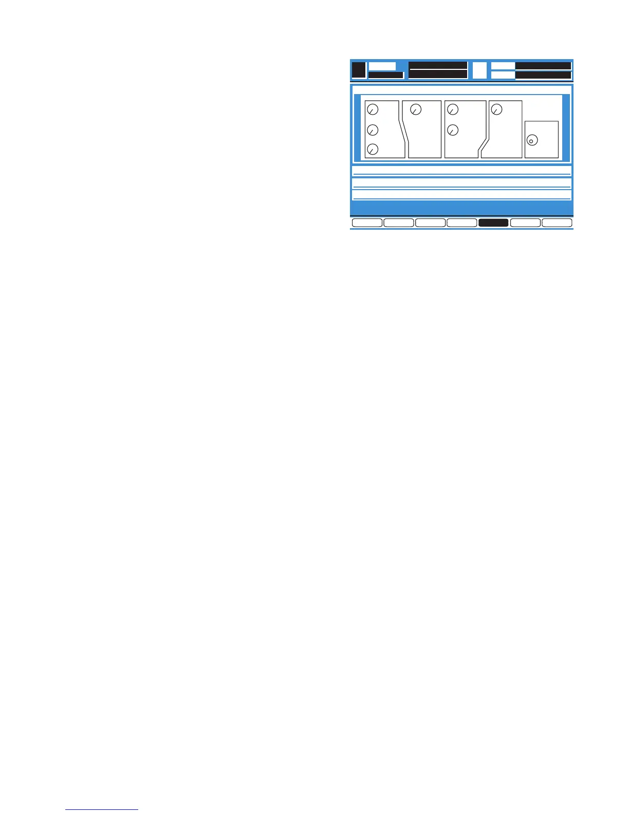
Press the Enter Key, the Diagnostic Menu 5 as shown in
Fig. 5-5 is displayed.
Fig. 5-5
8
Select the KNOB TEST Item by either UP or DOWN
Cursor.
8
Execute the KNOB TEST Item by pressing the Enter Key.
8
When executing, the Self Check will start for the Knobs.
First select the Q Adjusting Knob of the EQ Section
indicate to turn to right (reverse indication of the RIGHT).
8
Turn the Q Adjusting Knob to right, indicate to turn to the
left (reverse indication of LEFT).
8
Turn the Q Adjusting Knob to left, indicate to press this
Knob (reverse indication of KNOB).
If press the Enter Key instead of the Knob, this Knob will
be released reverse indication and next Knob becomes
reverse indication (Skip Function).
8
Press the Q Adjusting Knob, indicate to next Knob and
check the same manner as above.
8
The Jog Dial do not have press function.
8
The Self Check will be end after check of the Jog Dial.
5.15. LCD Test (LCD TEST)
8
Referring to Fig. 5-5, select the LCD TEST Item by either
UP or DOWN Cursor.
8
Execute the LCD TEST Item by pressing the Enter Key.
8
When executing, all face of the LCD is turn on (White
Indication) and off (Blue Indication) repeatedly by three
seconds.
8
Press the Enter Key to finish this Self Check Item.
5.16. Memory Initialize (MEMORY INITIALIZE)
8
Referring to Fig. 5-5, select the MEMORY INITIALIZE
Item by either UP or DOWN Cursor.
8
Execute the MEMORY INITIALIZE Item by pressing the
Enter Key.