AM1 • 14
TROUBLESHOOTING INSTRUCTIONS
While we had hoped that it wouldn’t come to this, if you are having trouble with
your transmitter, here are a few suggestions.
By far the most common sources of problems are misplaced parts or poor
solder connections. It’s always best to take a break before searching for bad
connections. Around here it’s referred to as the “Irwin Time Test” which states
that “anything left alone long enough seems to repair itself !” A good way of
checking component placement is to double check the assembly steps going
backwards from the last steps to the the first. Bright lighting and a magnifying
aid can be helpful in identifying soldering problems.
Use a methodical, logical troubleshooting technique. Most problems can be
solved using common sense. A volt-ohm meter and a clear head are usually
all that are needed to correct any problem. Please understand that it is nearly
impossible to “troubleshoot” by phone, any specific questions should be
documented and sent to us by mail.
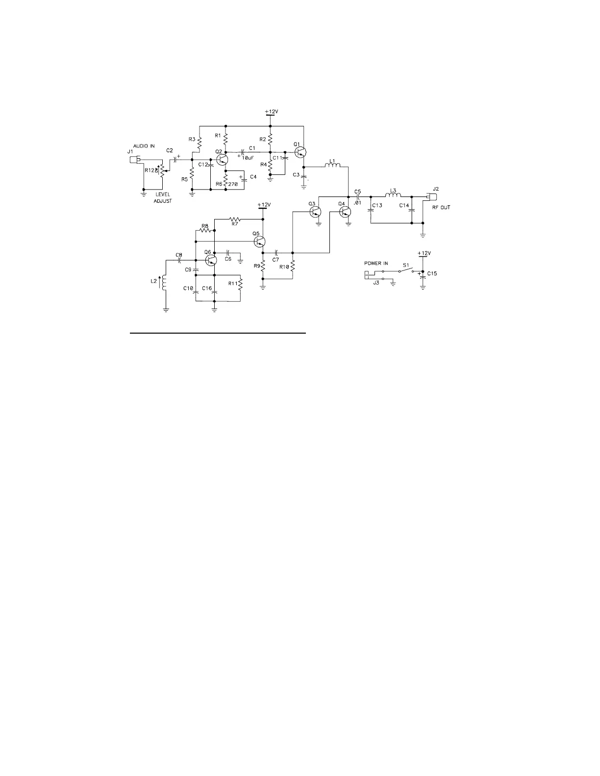
+1.1 V DC
+8.5 V DC
+ .4 VDC
+5.6 VDC
6.5 VDC
- 3.4 V DC
+3.2 VDC
POW ER " O N" I DL E C URRENT
NO MODULATION ~ 40 mA
APPROXIMATE DC VOLTAGES
AM - 1 KIT WIT H NO M ODULAT ION APPLI ED
1.2 VDC
8.5 VDC
3.4 VDC
OSCILLATOR AT 1600 KHz YOUR READINGS MAY DIFFER SLIGHTLY