AM1 • 5
output for the RF carrier frequency.
The audio input path is routed from J1, the audio input source, to transistor Q2
to amplify the incoming signal. Notice that the transistor is biased to be linear
using resistors R3, R5, and R6. The incoming audio signal is therefore
amplified undistorted (for great sounding audio). Optional capacitor C4 is used
only when a microphone input is used to provide additional gain from transistor
Q2. The audio input level to the amplifier can also be adjusted using R12, the
input level adjustment.
The resulting audio output is fed to transistor Q1, which does not provide any
gain, but supplies enough current to modulate the RF carrier. Inductor L1
allows the low frequency audio to pass through but “chokes” the RF signal and
does not allow it to get “back into” the audio circuitry.
Transistors Q3 and Q4 comprise the “power amplifier” section of the circuit.
Their collector supply voltage is furnished by Q1, thus producing an AM output
waveform. This signal is then low pass filtered using C13, C14, and L3.
Notice also that the audio information is applied at the power amplifier stage.
This is referred to as “high level” modulation, and is commonly used for high
power AM broadcast stations. The distinct advantage to this is that the RF
amplifiers need not be biased for linear operation. It is much cheaper to
manufacture a linear amplifier for the relatively low frequency audio, than to
produce the AM waveform at a low level and amplify it to a higher power level
without distortion. The main disadvantage of high level modulation is that the
audio modulator’s power must be half that of the final transmitter, not too tough
for our low power kit, but try to imagine the amplifier for a 50,000 watt AM
broadcast station! Boy, that audio amp would sure crank the ‘ol car stereo!
It should also be stated that, due to the linear operation of the amplifiers in this
circuit (transistors Q1 and Q2 biased “on”), this circuit will consume some
power. It is not recommended that a common rectangular 9V battery be used
to power this kit. Instead, a battery “pack” consisting of eight 1.5 volt cells, a
12V sealed battery, or other external 12V DC supply may be used.
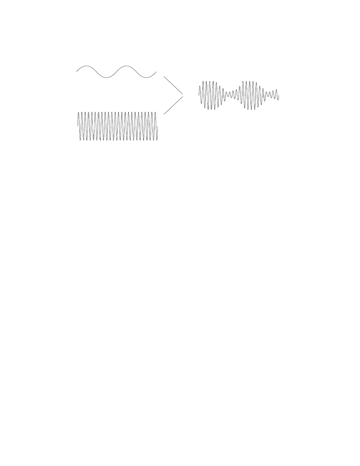
Low Frequency Audio Waveform
High Frequency Radio Carrier
Amplitude Modulated Signal