5
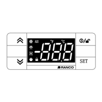
Optional Display
To minimize temperature alarms during start up, defrost, and temperature fluctuations, alarm delay timers can be configured. The controllers can be
configured to start defrosting based on the elapsed system-on time, the accumulated run time of the compressor, or the difference in temperature between
the evaporator sensor and the control sensor. Defrosting can be terminated by elapsed time, the evaporator or control temperature sensor, or by a
temperature switch. If the control temperature sensor fails, the compressor can be powered on, powered off, or follow a configured duty cycle.
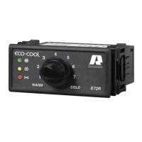
The controllers include the following physical features:
• Knob for setpoint adjustment
• Two temperature sensor inputs for a control probe and an evaporator probe
• One digital input for an optional defrost termination switch
• E71R Controller: One relay for a refrigeration compressor
• E72R Controller: One relay for a refrigeration compressor and one relay for a defrost heater and fan
• 90V to 240V AC switching power supply
• Connection for configuration or optional display
• Plastic enclosure and compact size for easy installation in most appliances
• Customizable control parameters
• Flash-memory microprocessor for quick and inexpensive configuration and firmware downloads at the factory or in the field
• Adjustable mounting clips for panel or bracket mounting
4 INSTALLATION
4.1 Installing the controller
The controller can be mounted in a panel cutout with the LEDs showing, mounted behind a panel with only the adjustment shaft exposed, or mounted
completely within the case.
To mount the controller with the face exposed, cut a 2 26/32” by 1 5/32” (71 mm x 29 mm) hole in the panel. Insert the controller from the outside of the
panel and slide a mounting clip onto each side of the controller from behind the panel.
Optionally, the controller can be mounted to a bracket inside the case.
Type E7 EcoCool™ Electronic Temperature and Defrost Controllers
©2008 Invensys Controls All rights reserved.
DRAFT VERSION