7
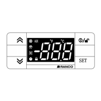
4.2 Mounting the display
The optional display can be flush mounted in a panel cutout up to 30ft (10m) from the controller. To mount the display flush to the panel, cut a 2.32” by 1”
(64mm x 31mm) hole in the panel. Insert the display from the outside of the panel. Friction tabs on the sides of the display hold it in place.
4.3 Wiring the display
Use the Interface Box, Copy Card, and Display TTL Connector on the controller to connect to the display.
5 FUNCTIONS AND FEATURES
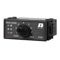
5.1.1 User control
The adjustment knob can be rotated to select any control temperature within the configured range.
The OFF and ON positions of the adjustment knob can be set to specific angles relative to full counter clockwise. Rotating the adjustment knob fully counter
clockwise (to OFF) powers off the controller and compressor immediately. However, hazardous voltage remains. The controller, compressor, defrost heater,
and defrost fan must be disconnected, prior to service, using a separate switch. If the On/Off Function is enabled and the knob is in the OFF position, rotating
the knob clockwise powers on the controller.
5.1.2 Control mode
The controller cycles the compressor or refrigeration solenoid valve to maintain the selected control temperature.
The warm and cold adjustment knob positions are configured using four setpoints. Cut-In Warm and Cut-Out Warm are the setpoints for the warm position.
Cut-In Cold and Cut-Out Cold are the setpoints for the cold position. The cold position is full clockwise rotation. The warm position is full counter clockwise
rotation or, if the On/Off Function is enabled, the specified angle. When the user sets the adjustment knob to a setpoint between the warm and cold
positions, the Cut-In and Cut-Out setpoints are calculated by the controller. The setpoints can be configured using Celsius or Fahrenheit units.
Type E7 EcoCool™ Electronic Temperature and Defrost Controllers
©2008 Invensys Controls All rights reserved.
DRAFT VERSION