Preparing for use
R&S
®
NRP Series
18Getting Started 1419.0170.02 ─ 16
●
1 R&S NRP‑ZK6 cable per sensor
●
R&S NRP‑Z5 sensor hub with external power supply unit and USB cable
●
BNC cables to connect the trigger input and trigger output signals (optional)
Setup
1
2
3
4
8
9
7
65
NRP
3-Path Diode Power Sensor
MHz to GHz, 100 pW to 200 mW (−70 dBm to +23 dBm)
SMART SENSOR TECHNOLOGY
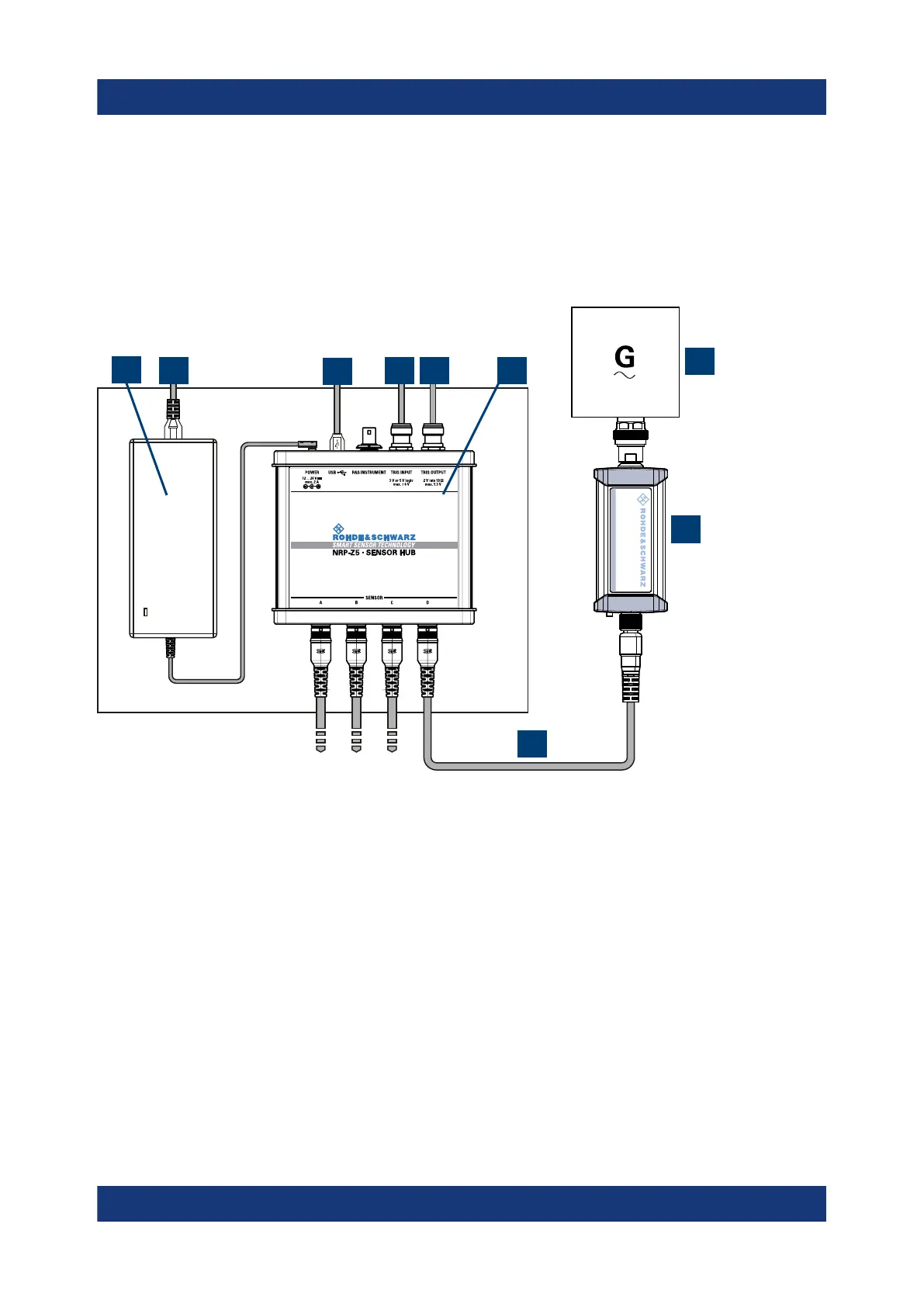
Figure 3-2: Setup with an R&S NRP-Z5 sensor hub
1 = External power supply unit
2 = Connect to AC power supply.
3 = Connect to computer with USB host interface.
4 = Optional: Connect to trigger source.
5 = Optional: Connect to triggered device.
6 = R&S NRP‑Z5 sensor hub
7 = Signal source (DUT)
8 = R&S NRP power sensor
9 = R&S NRP‑ZK6 cable
Set up as shown in Figure 3-2.
1. Connect the R&S NRP‑ZK6 cable to the power sensor. See "To connect a
cable to the host interface of the power sensor" on page 15.
Connecting to a controlling host
 Loading...


