Preparing the Analyzer for Use
R&S
®
ZVA
16Getting Started 1145.1090.62 ─ 13
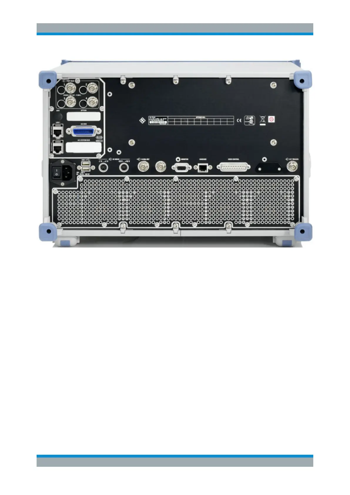
Fig. 1-2: R&S ZVA rear view
The rear connectors are described in detail in the annex "Hardware Interfaces" in the
help system.
●
The PORT BIAS panel contains inputs for an external DC voltage (bias) to be
applied to the test ports. A separate input is provided for each test port. Each
PORT BIAS input is protected by an exchangeable fuse.
●
IEC Bus is the GPIB bus connector (according to standard IEEE 488 / IEC 625).
●
AUX is an auxiliary connector, to be wired as needed. AUX is not fitted on standard
instruments.
●
LAN 1 and LAN 2 are two equivalent connectors to connect the analyzer to a Local
Area Network.
●
USB is a double Universal Serial Bus connector of type A (master USB), used to
connect a keyboard, mouse or other pointing device.
●
DC MEAS comprises two inputs for DC measurements, specified for different volt-
age ranges.
●
10 MHz REF serves as an input or output for the 10 MHz reference clock signal.
●
MONITOR is a sub-Min-D connector used to connect an external VGA monitor.
●
CASCADE is a 8-pin RJ-45 connector used as output and input connectors for
pulse generator signals. The CASCADE connector is located between the MONI-
TOR and the USER CONTROL connectors.
Rear Panel Tour

 Loading...


