System Overview
R&S
®
ZVA
78Getting Started 1145.1090.62 ─ 13
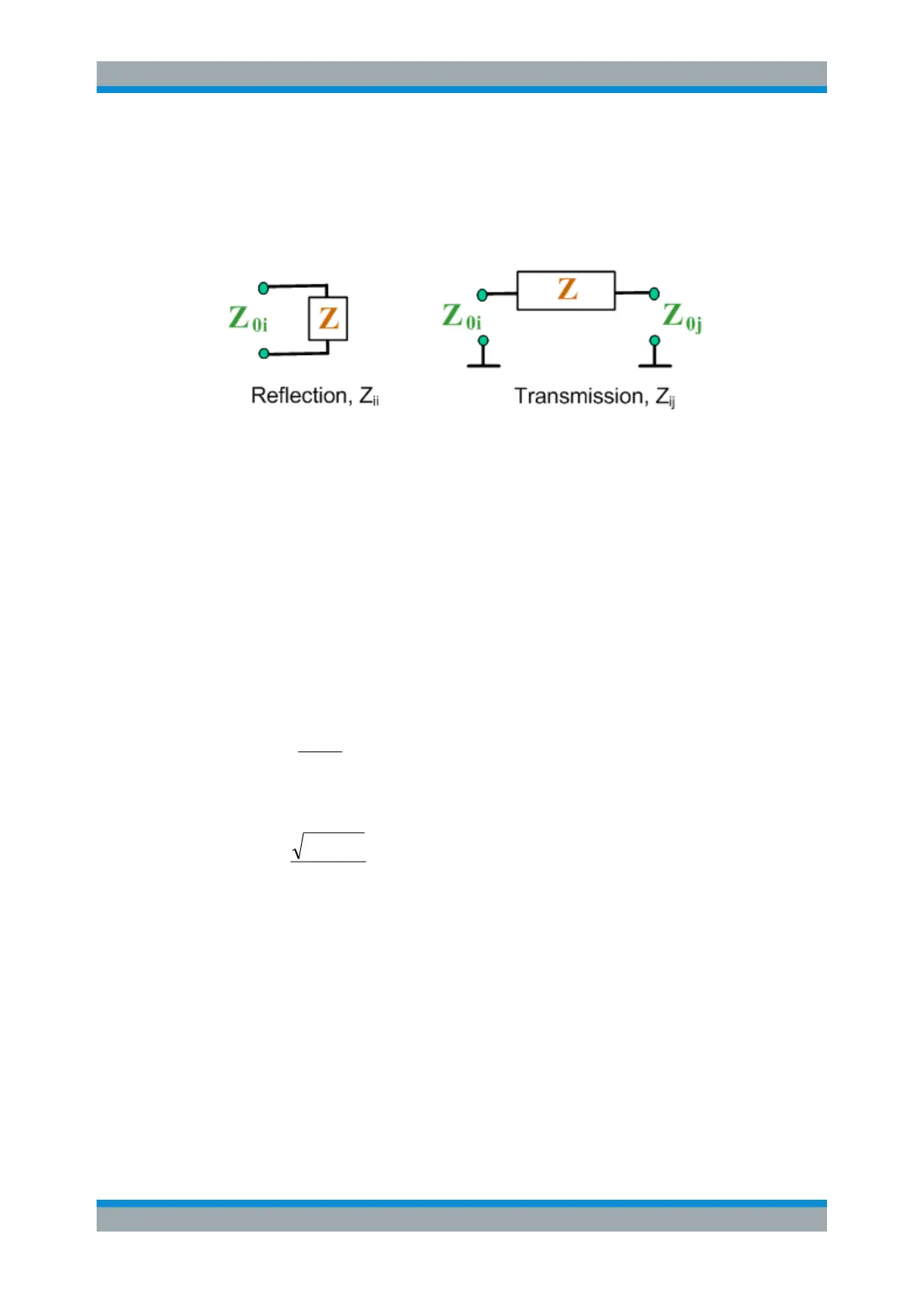
3.3.2.1 Converted Impedances
The converted impedance parameters describe the input impedances of a DUT with
fully matched outputs. In the figures below the indices I and j number the analyzer/DUT
ports, Z
0i
is the reference impedance at the DUT port I.
The analyzer converts a single measured S-parameter to determine the corresponding
converted impedance. As a result, converted Z-parameters cannot completely describe
general n-port DUTs:
●
A reflection parameter Z
ii
completely describes a one-port DUT. For n-port DUTs
(n>1) the reflection parameters Z
ii
describe the input impedances at ports I (I = 1 to
n) under the condition that each of the other ports is terminated with its reference
impedance (matched-circuit parameters).
●
A two-port transmission parameter Z
ij
(i ≠ j) can describe a pure serial impedance
between the two ports.
Relation with S-parameters
The converted impedances Z
ii
are calculated from the reflection S-parameters S
ii
according to:
The transmission parameters are calculated according to:
,,2
00
00
jiZZ
S
ZZ
Z
ji
ij
ji
ij
The converted admittances are defined as the inverse of the impedances.
Examples:
●
Z
11
is the input impedance of a 2-port DUT that is terminated at its output with the
reference impedance Z
0
(matched-circuit impedance measured in a forward reflec-
tion measurement).
●
The extension of the impedances to more ports and mixed mode measurements is
analogous to S-parameters. Z
dd44
is the differential mode input impedance at port 4
of a DUT that is terminated at its other ports with the reference impedance Z
0
.
Measured Quantities
 Loading...


