Manual-3
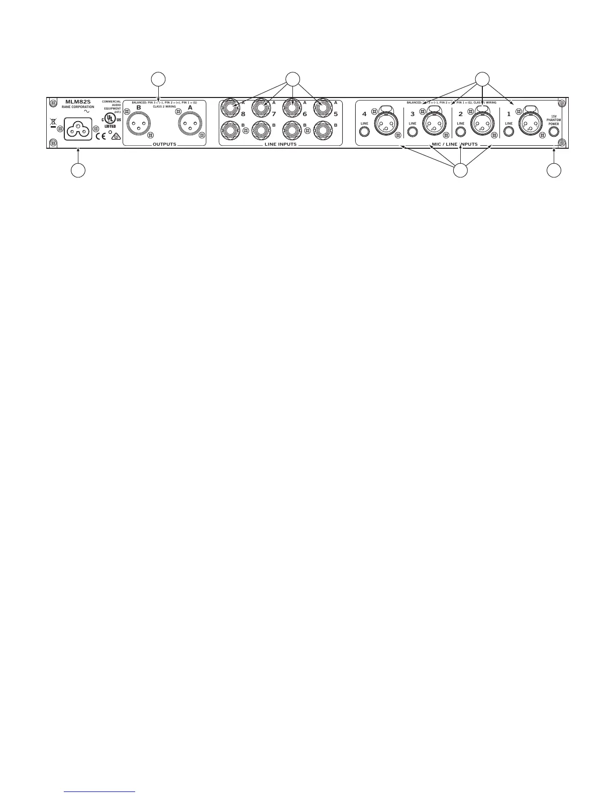
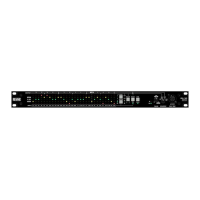
REAR PANEL DESCRIPTION
1 MIC/LINE INPUTS 1 through 4. ese XLRs connect either balanced Microphone or Line signals, depending on the LINE
switch setting (see 3). Rane adheres to the international and U.S. standard for balanced pin congurations: Pin 1 is chassis
ground (neutral), pin 2 is positive (+), and pin 3 is negative (–).
2 PHANTOM POWER switch applies 15 V Phantom Power to any Inputs 1-4 that are set for MIC Input.
3 LINE Input selectors switch the sensitivity and input impedance for either a microphone or line level input. If LINE is chosen,
Phantom Power is deactivated for that Input.
4 ¼" LINE INPUTS. ese stereo pairs of balanced inputs accommodate stereo line-level signals. ese TRS (Tip-Ring-Sleeve) ¼"
jacks handle either balanced or unbalanced signals. In most cases an unbalanced signal may use a mono ¼" plug (Tip-Sleeve). See
the Sound System Interconnection RaneNote included with this manual for proper connection.
5 A and B OUTPUT jacks. ese balanced XLR’s provide the A and B mixed output. INTERNAL OUTPUT LEVEL switches
allow setting the output level for MIC or LINE level. Pin connections are the same as above in 1.
6 Power connector: e internal universal switching power supply operates on any AC mains 100 to 240 VAC, 50 or 60 Hz (most
places in the world). All that is required when traveling is the appropriate IEC line cord.
BALANCED:
PIN 3 =
(–),
PIN 2 =
(+),
PIN 1 = (G)
CLASS 2 WIRING
BALANCED:
PIN 3 =
(–),
PIN 2 =
(+),
PIN 1 = (G), CLASS 2 WIRING
100-240 V
50/60 Hz 7 WATTS
COMMERCIAL
AUDIO
EQUIPMENT
24TJ
R
6 23
5
14