32
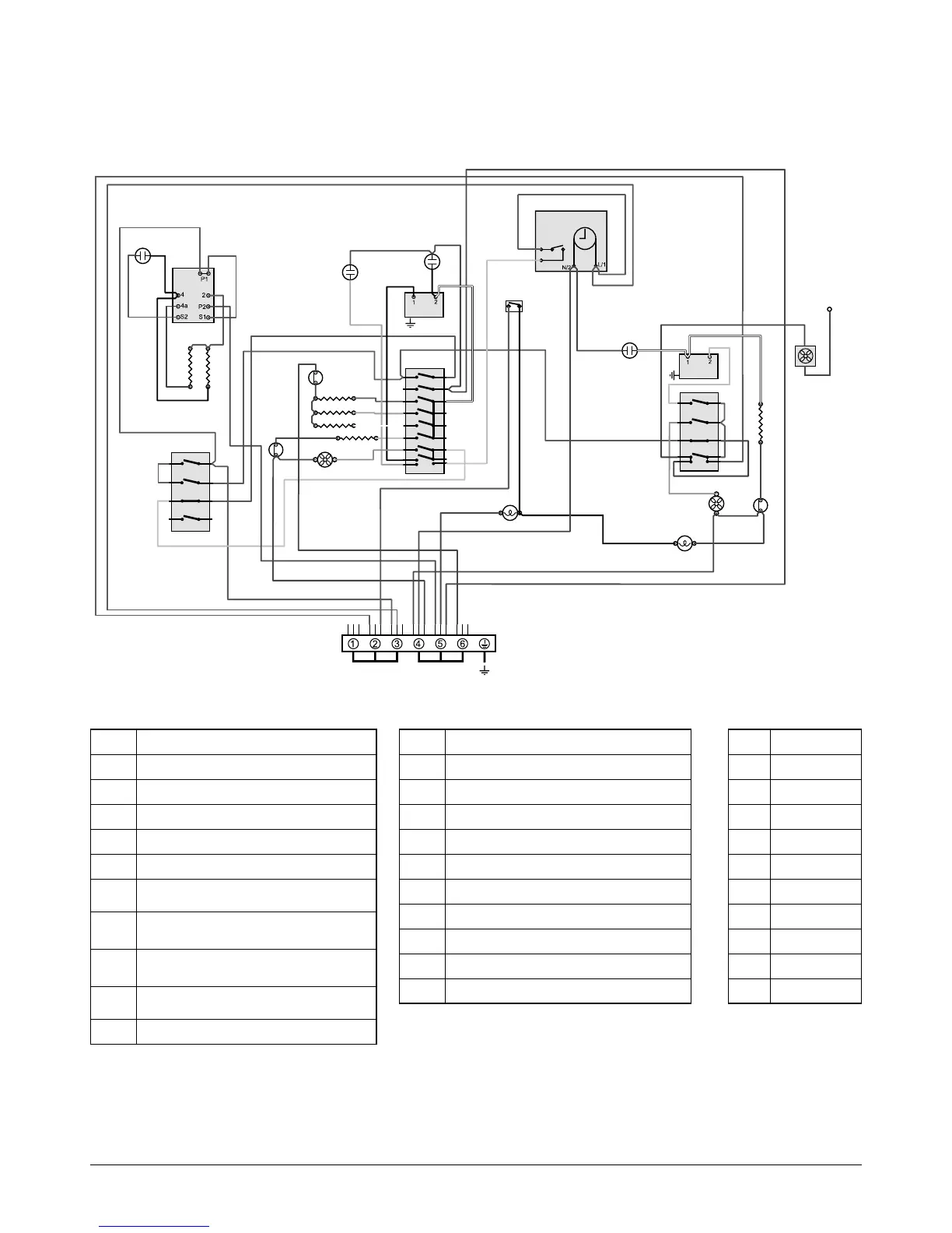
The connections shown in the circuit diagram are for single- phase. The ratings are for 230 V 50 Hz.
P033458
2
3
4
1
P3
P2
P1
P4
P033458
2
3
4
1
P3
P2
P1
P4
P028728
6
P6
5 P5
4
P4
7 P7
8 P8
2
P2
1
P1
3 P3
L N
E
w w
or
bk
b
br
bk
b
br
bk
br
br
b
b
b
b
b
br
v
v
v
w
b
y
y
br
br
y
y
y
v
r
br br
br
b
b
r
r
b
b
bk
w
b
r
w
gy
r
gy
w
bk
or
y
br
br
br
bb
br
To terminal P6
on the warmer
hob controller
switch
br
v
b
b
y
y
b
br
br
br
br
b
b
b
b
b
r
br
br
br
br
b
bk
gy
v
bk
bk
r
br
bk
b
or
b
or
A2
A1
B1
A3
B3
B4
B2
B5
B6
B7
I
D
F1
G
K
I
H
E
F2
F3
F4
K
K
K
J
J
J
Code Description
A1 Grill energy regulator
A2 Grill elements
A3 Grill front switch
B1 Left-hand multi-function oven thermostat
B2 Left-hand multi-function oven control
B3
Left-hand multi-function oven base
element
B4
Left-hand multi-function oven top
element (outer pair)
B5
Left-hand multi-function oven browning
element (inner pair)
B6
Left-hand multi-function oven fan
element
B7 Left-hand multi-function oven fan
Code Description
D Clock
F1 Right-hand oven thermostat
F2 Right-hand oven front switch
F3 Right-hand oven element
F4 Right-hand oven fan
G Cooling fan
H Light switch
I Oven light
J
Thermal cut -out
K Neon
Multifunction Oven
Elan
Code Colour
b Blue
br Brown
bk Black
or Orange
r Red
v Violet
w White
y Yellow
g/y Green/yellow
gy Grey